|
|
| Line 1: |
Line 1: |
| − | ==PFAS Sources== | + | ==Estimating PCE/TCE Abiotic First-Order Reductive Dechlorination Rate Constants in Clayey Soils Under Anoxic Conditions== |
| − | [[Perfluoroalkyl and Polyfluoroalkyl Substances (PFAS)]] have been used in coatings for textiles, paper products, and cookware; in some firefighting foams; and have a range of applications in the aerospace, photographic imaging, semiconductor, automotive, construction, electronics, and aviation industries<ref name="ITRC2020">Interstate Technology and Regulatory Council (ITRC), 2020. Technical/Regulatory Guidance: Per- and Polyfluoroalkyl Substances (PFAS), PFAS-1. ITRC, PFAS Team, Washington DC. Website: https://pfas-1.itrcweb.org/ [https://pfas-1.itrcweb.org/wp-content/uploads/2020/04/ITRC_PFAS_TechReg_April2020.pdf Free Download from ITRC]. [[Media: ITRC_PFAS-1.pdf | Report.pdf]]</ref><ref name="KEMI2015">Swedish Chemicals Agency (KEMI), 2015. Occurrence and use of highly fluorinated substances and alternatives, Report 7/15. ISSN 0284-1185. Article number 361 164. [[Media: KEMI2015.pdf | Report.pdf]]</ref><ref name="USEPA2021">US Environmental Protection Agency (USEPA), 2021. Basic Information on PFAS. [https://www.epa.gov/pfas/basic-information-pfas#tab-1 Website]</ref>. Although PFAS and PFAS-containing products have been manufactured since the 1950s, PFAS were not widely documented in environmental samples until the early 2000s. Understanding PFAS manufacturing history, past and current uses, and waste management over the last six to seven decades is necessary for the identification of potential environmental sources of PFAS, possible release mechanisms, and associated pathway-receptor relationships.
| + | The U.S. Department of Defense (DoD) faces many challenges in restoring aquifers at contaminated sites, often due to back-diffusion of tetrachloroethene (PCE) and trichloroethene (TCE) from low-permeability clay zones. The uptake, storage, and subsequent long-term release of these dissolved contaminants from clays are key processes in understanding the longevity, intensity, and risks associated with many persistent chlorinated ethene groundwater plumes. Although naturally occurring abiotic and biotic dechlorination processes in clays may reduce stored contaminant mass and significantly aid natural attenuation, no standardized field method currently exists to verify or quantify these reactions. It is critical to remediation design efforts to demonstrate and validate a cost-effective in situ approach for assessing these dechlorination processes using first-order rate constants. An approach was developed and applied across eight DoD sites to support Remedial Project Managers (RPMs) and regulators in evaluating natural attenuation potential in clay-rich environments. |
| | <div style="float:right;margin:0 0 2em 2em;">__TOC__</div> | | <div style="float:right;margin:0 0 2em 2em;">__TOC__</div> |
| | | | |
| | '''Related Article(s):''' | | '''Related Article(s):''' |
| | | | |
| − | * [[Perfluoroalkyl and Polyfluoroalkyl Substances (PFAS)]] | + | *[[Monitored Natural Attenuation (MNA)]] |
| − | * [[PFAS Transport and Fate]] | + | *[[Monitored Natural Attenuation (MNA) of Chlorinated Solvents]] |
| | + | *[[Monitored Natural Attenuation - Transitioning from Active Remedies]] |
| | + | *[[Matrix Diffusion]] |
| | + | *[[REMChlor - MD]] |
| | | | |
| − | '''Contributor(s):''' [[Dr. Sheau-Yun (Dora) Chiang]] and [[Dr. Alexandra Salter-Blanc]] | + | '''Contributors:''' Dani Tran, Dr. Charles Schaefer, Dr. Charles Werth |
| | | | |
| − | '''Key Resource(s):''' | + | '''Key Resource:''' |
| − | | + | *Schaefer, C.E, Tran, D., Nguyen, D., Latta, D.E., Werth, C.J., 2025. Evaluating Mineral and In Situ Indicators of Abiotic Dechlorination in Clayey Soils<ref name="SchaeferEtAl2025"/> |
| − | *[https://pfas-1.itrcweb.org/wp-content/uploads/2020/04/ITRC_PFAS_TechReg_April2020.pdf Per- and Polyfluoroalkyl Substances (PFAS), PFAS-1. ITRC 2020.]<ref name="ITRC2020"/> | |
| | | | |
| | ==Introduction== | | ==Introduction== |
| − | [[Perfluoroalkyl and Polyfluoroalkyl Substances (PFAS)]] are a complex family of more than 3,000 manmade fluorinated organic chemicals<ref name="Wang2017">Wang, Z., DeWitt, J.C., Higgins, C.P., and Cousins, I.T., 2017. A Never-Ending Story of Per- and Poly-Fluoroalkyl Substances (PFASs)? Environmental Science and Technology, 51(5), pp. 2508-2518. [https://doi.org/10.1021/acs.est.6b04806 DOI: 10.1021/acs.est.6b04806] [[Media: Wang2017.pdf | Open access article.]]</ref> although not all of these are currently in use or production. PFAS are produced using several different processes. Fluorosurfactants, which include perfluoroalkyl acids (PFAAs) (see [[Perfluoroalkyl and Polyfluoroalkyl Substances (PFAS) | PFAS]] article for nomenclature) and side-chain fluorinated polymers, have been manufactured using two major processes: [[Wikipedia: Electrochemical fluorination | electrochemical fluorination (ECF)]] and [[Wikipedia: Telomerization | telomerization]]<ref name="KEMI2015"/>. ECF was licensed by 3M in the 1940s<ref name="Banks1994">Banks, R.E., Smart, B.E. and Tatlow, J.C. eds., 1994. Organofluorine Chemistry: Principles and Commercial Applications. Springer Science and Business Media, New York, N. Y. [https://link.springer.com/book/10.1007/978-1-4899-1202-2 DOI: 10.1007/978-1-4899-1202-2]</ref> and used by 3M until 2001. ECF produces a mixture of even and odd numbered carbon chain lengths of approximately 70% linear and 30% branched substances<ref name="Concawe2016">Concawe (Conservation of Clean Air and Water in Europe), 2016. Environmental fate and effects of poly- and perfluoroalkyl substances (PFAS). Report No. 8/16. Brussels, Belgium. [[Media:Concawe2016.pdf | Report.pdf]]</ref>. Telomerization was developed in the 1970s<ref name="Benskin2012a">Benskin, J.P., Ahrens, L., Muir, D.C., Scott, B.F., Spencer, C., Rosenberg, B., Tomy, G., Kylin, H., Lohmann, R. and Martin, J.W., 2012. Manufacturing Origin of Perfluorooctanoate (PFOA) in Atlantic and Canadian Arctic Seawater. Environmental Science and Technology, 46(2), pp. 677-685. [https://doi.org/10.1021/es202958p DOI: 10.1021/es202958p]</ref>, and yields mainly even numbered, straight carbon chain isomers<ref name="Kissa2001">Kissa, E., 2001. Fluorinated Surfactants and Repellents, Second Edition. Surfactant Science Series, Vol. 97. Marcel Dekker, Inc., CRC Press, New York. 640 pages. ISBN: 9780824704728</ref><ref name="Parsons2008">Parsons, J.R., Sáez, M., Dolfing, J. and De Voogt, P., 2008. Biodegradation of Perfluorinated Compounds. Reviews of Environmental Contamination and Toxicology, 196, pp. 53-71. Springer, New York, NY. [https://doi.org/10.1007/978-0-387-78444-1_2 DOI: 10.1007/978-0-387-78444-1_2] Free download from: [https://www.researchgate.net/profile/Jan_Dolfing/publication/23489065_Biodegradation_of_Perfluorinated_Compounds/links/0912f5087a40c9d5df000000.pdf ResearchGate]</ref>. PFAS manufacturers have provided PFAS to secondary manufacturers for production of a vast array of industrial and consumer products.
| + | Cost-effective methods are needed to verify the occurrence of natural dechlorination processes and quantify their dechlorination rates in clays under ambient in situ conditions in order to reliably predict their long-term influence on plume longevity and mass discharge. However, accurately determining these rates is challenging due to slow reaction kinetics, the transient nature of transformation products, and the interplay of biotic and abiotic mechanisms within the clay matrix or at clay-sand interfaces. Tools capable of quantifying these reactions and assessing their role in mitigating plume persistence would be a significant aid for long-term site management. |
| − | | |
| − | During manufacturing, PFAS may be released into the atmosphere then redeposited on land where they can also affect surface water and groundwater, or PFAS may be discharged without treatment to wastewater treatment plants or landfills, and eventually be released into the environment by treatment systems that are not designed to mitigate PFAS (see also [[PFAS Transport and Fate]]). Industrial discharges of PFAS were unregulated for many years, but that has begun to change. In January 2016, New York became the first state in the nation to regulate PFOA as a hazardous substance followed by the regulation of PFOS in April 2016. Consumer and industrial uses of PFAS-containing products can also end up releasing PFAS into landfills and into municipal wastewater, where it may accumulate undetected in biosolids which are typically treated by land application.
| |
| − | | |
| − | ==Industrial Sources==
| |
| − | PFAS are used in many industrial and consumer applications, which may have released PFAS into the environment and impacted drinking water supplies in many areas of the United States<ref name="EWG2017">Environmental Working Group (EWG) and Northeastern University Social Science Environmental Health Research Institute, 2017. Mapping A Contamination Crisis. [https://www.ewg.org/research/mapping-contamination-crisis Website]</ref>. Both in the United States (US) and abroad, primary manufacturing facilities produce PFAS and secondary manufacturing facilities use PFAS to produce goods. Environmental release mechanisms associated with these facilities include air emission and dispersion, spills, and disposal of manufacturing wastes and wastewater. Potential impacts to air, soil, sediment, surface water, stormwater, and groundwater are present not only at primary release points but potentially over the surrounding area<ref name="Shin2011">Shin, H.M., Vieira, V.M., Ryan, P.B., Detwiler, R., Sanders, B., Steenland, K., and Bartell, S.M., 2011. Environmental Fate and Transport Modeling for Perfluorooctanoic Acid Emitted from the Washington Works Facility in West Virginia. Environmental Science and Technology, 45(4), pp. 1435-1442. [https://doi.org/10.1021/es102769t DOI: 10.1021/es102769t]</ref>. Some of the potential primary and secondary sources of PFAS releases to the environment are listed here<ref name="ITRC2020"/>:
| |
| − | | |
| − | * '''Textiles and leather:''' Factory or consumer applied coating to repel water, oil, and stains. Applications include protective clothing and outerwear, umbrellas, tents, sails, architectural materials, carpets, and upholstery<ref name="Rao1994">Rao, N.S., and Baker, B.E., 1994. Textile Finishes and Fluorosurfactants. In: Organofluorine Chemistry, Banks, R.E., Smart, B.E., and Tatlow, J.C., Eds. Springer, New York. [https://doi.org/10.1007/978-1-4899-1202-2_15 DOI: 10.1007/978-1-4899-1202-2_15]</ref><ref name="Hekster2003">Hekster, F.M., Laane, R.W. and De Voogt, P., 2003. Environmental and Toxicity Effects of Perfluoroalkylated Substances. Reviews of Environmental Contamination and Toxicology, 179, pp. 99-121. Springer, New York, NY. [https://doi.org/10.1007/0-387-21731-2_4 DOI: 10.1007/0-387-21731-2_4]</ref><ref name="Brooke2004">Brooke, D., Footitt, A., and Nwaogu, T.A., 2004. Environmental Risk Evaluation Report: Perfluorooctanesulphonate (PFOS). Environment Agency (UK), Science Group. Free download from: [http://chm.pops.int/Portals/0/docs/from_old_website/documents/meetings/poprc/submissions/Comments_2006/sia/pfos.uk.risk.eval.report.2004.pdf The Stockholm Convention] [[Media:Brooke2004.pdf | Report.pdf]]</ref><ref name="Poulsen2005">Poulsen, P.B., Jensen, A.A., and Wallström, E., 2005. More environmentally friendly alternatives to PFOS-compounds and PFOA. Danish Environmental Protection Agency, Environmental Project 1013. [[Media: Poulsen2005.pdf | Report.pdf]]</ref><ref name="Prevedouros2006">Prevedouros, K., Cousins, I.T., Buck, R.C. and Korzeniowski, S.H., 2006. Sources, Fate and Transport of Perfluorocarboxylates. Environmental Science and Technology, 40(1), pp. 32-44. [https://doi.org/10.1021/es0512475 DOI: 10.1021/es0512475] Free download from: [https://www.academia.edu/download/39945519/Sources_Fate_and_Transport_of_Perfluoroc20151112-1647-19vcvbf.pdf Academia.edu]</ref><ref name="Walters2006">Walters, A., and Santillo, D., 2006. Technical Note 06/2006: Uses of Perfluorinated Substances. Greenpeace Research Laboratories. [http://www.greenpeace.to/publications/uses-of-perfluorinated-chemicals.pdf Website] [[Media: Walters2006.pdf | Report.pdf]]</ref><ref name="Trudel2008">Trudel, D., Horowitz, L., Wormuth, M., Scheringer, M., Cousins, I.T. and Hungerbühler, K., 2008. Estimating Consumer Exposure to PFOS and PFOA. Risk Analysis: An International Journal, 28(2), pp. 251-269. [https://doi.org/10.1111/j.1539-6924.2008.01017.x DOI: 10.1111/j.1539-6924.2008.01017.x]</ref><ref name="Guo2009">Guo, Z., Liu, X., Krebs, K.A. and Roache, N.F., 2009. Perfluorocarboxylic Acid Content in 116 Articles of Commerce, EPA/600/R-09/033. National Risk Management Research Laboratory, US Environmental Protection Agency, Washington, DC. Available from: [https://cfpub.epa.gov/si/si_public_record_report.cfm?Lab=NRMRL&dirEntryId=206124 US EPA.] [[Media: Guo2009.pdf | Report.pdf]]</ref><ref name="USEPA2009">US Environmental Protection Agency (USEPA), 2009. Long-Chain Perfluorinated Chemicals (PFCs), Action Plan. [https://www.epa.gov/sites/production/files/2016-01/documents/pfcs_action_plan1230_09.pdf Website] [[Media: USEPA2009.pdf | Report.pdf]]</ref><ref name="Ahrens2011a">Ahrens, L., 2011. Polyfluoroalkyl compounds in the aquatic environment: a review of their occurrence and fate. Journal of Environmental Monitoring, 13(1), pp.20-31.
| |
| − | [http://dx.doi.org/10.1039/C0EM00373E DOI: 10.1039/C0EM00373E]. Free download available from: [https://www.researchgate.net/profile/Lutz_Ahrens/publication/47622154_Polyfluoroalkyl_compounds_in_the_aquatic_environment_A_review_of_their_occurrence_and_fate/links/00b7d53762cfedaf12000000/Polyfluoroalkyl-compounds-in-the-aquatic-environment-A-review-of-their-occurrence-and-fate.pdf ResearchGate]</ref><ref name="Buck2011">Buck, R.C., Franklin, J., Berger, U., Conder, J.M., Cousins, I.T., De Voogt, P., Jensen, A.A., Kannan, K., Mabury, S.A. and van Leeuwen, S.P., 2011. Perfluoroalkyl and Polyfluoroalkyl Substances in the Environment: Terminology, Classification, and Origins. Integrated Environmental Assessment and Management, 7(4), pp. 513-541. [https://doi.org/10.1002/ieam.258 DOI: 10.1002/ieam.258] [[Media:Buck2011.pdf | Open access article.]]</ref><ref name="UNEP2011">United Nations Environmental Programme (UNEP), 2011. Report of the persistent organic pollutants review committee on the work of its sixth meeting, Addendum, Guidance on alternatives to perfluorooctane sulfonic acid and its derivatives, UNEP/POPS/POPRC.6/13/Add.3/Rev.1 [http://www.pops.int/TheConvention/POPsReviewCommittee/Meetings/POPRC6/POPRC6Documents/tabid/783/ctl/Download/mid/3507/Default.aspx?id=125 Website] [[Media: UNEP2011.pdf | Report.pdf]]</ref><ref name="Herzke2012">Herzke, D., Olsson, E. and Posner, S., 2012. Perfluoroalkyl and polyfluoroalkyl substances (PFASs) in consumer products in Norway – A pilot study. Chemosphere, 88(8), pp. 980-987. [https://doi.org/10.1016/j.chemosphere.2012.03.035 DOI: 10.1016/j.chemosphere.2012.03.035]</ref><ref name="Patagonia2016">Patagonia, Inc., 2016. An Update on Our DWR Problem. [https://www.patagonia.com/stories/our-dwr-problem-updated/story-17673.html Website] [[Media: Patagonia2016.pdf | Report.pdf]]</ref><ref name="Kotthoff2015">Kotthoff, M., Müller, J., Jürling, H., Schlummer, M., and Fiedler, D., 2015. Perfluoroalkyl and polyfluoroalkyl substances in consumer products. Environmental Science and Pollution Research, 22(19), pp. 14546-14559. [https://doi.org/10.1007/s11356-015-4202-7 DOI: 10.1007/s11356-015-4202-7] [[Media: Kotthoff2015.pdf | Open access article.]]</ref><ref name="ATSDR2018">Agency for Toxic Substances and Disease Registry (ATSDR), 2018. Toxicological Profile for Perfluoroalkyls, Draft for Public Comment. US Department of Health and Human Services. Free download from: [http://www.atsdr.cdc.gov/toxprofiles/tp200.pdf ATSDR] [[Media: ATSDR2018.pdf | Report.pdf]]</ref>.
| |
| − | | |
| − | * '''Paper products:''' Surface coatings to repel grease and moisture. Uses include non-food paper packaging (for example, cardboard, carbonless forms, masking papers) and food-contact materials (for example, pizza boxes, fast food wrappers, microwave popcorn bags, baking papers, pet food bags)<ref name="Rao1994"/><ref name="Kissa2001"/><ref name="Hekster2003"/><ref name="Poulsen2005"/><ref name="Trudel2008"/><ref name="Buck2011"/><ref name="UNEP2011"/><ref name="Kotthoff2015"/><ref name="Schaider2017">Schaider, L.A., Balan, S.A., Blum, A., Andrews, D.Q., Strynar, M.J., Dickinson, M.E., Lunderberg, D.M., Lang, J.R., and Peaslee, G.F., 2017. Fluorinated Compounds in US Fast Food Packaging. Environmental Science and Technology Letters, 4(3), pp. 105-111. [https://doi.org/10.1021/acs.estlett.6b00435 DOI: 10.1021/acs.estlett.6b00435] [[Media: Schaider2017.pdf | Open access article.]]</ref>
| |
| − | | |
| − | * '''Metal Plating & Etching:''' Corrosion prevention, mechanical wear reduction, aesthetic enhancement, surfactant, wetting agent/fume suppressant for chrome, copper, nickel and tin electroplating, and post-plating cleaner<ref name="USEPA1996">US Environmental Protection Agency (USEPA), 1996. Emission Factor Documentation for AP-42, Section 12.20. Office of Air Quality Planning and Standards, Emission Factor and Inventory Group, Research Triangle Park, NC. [[Media: USEPA1996.pdf | Report.pdf]]</ref><ref name="Riordan1998">Riordan, B.J., Karamchandanl, R.T., Zitko, L.J., and Cushnie Jr., G.C., 1998. Capsule Report: Hard Chrome Fume Suppressants and Control Technologies. Center for Environmental Research Information, National Risk Management Research Laboratory, Office of Research and Development. EPA/625/R-98/002 [https://cfpub.epa.gov/si/si_public_record_Report.cfm?Lab=NRMRL&dirEntryID=115419 Website] [[Media: Riordan1998.pdf | Report.pdf]]</ref><ref name="Kissa2001"/><ref name="Prevedouros2006"/><ref name="USEPA2009a">US Environmental Protection Agency (USEPA), 2009. PFOS Chromium Electroplater Study. US EPA – Region 5, Chicago, IL. [[Media: USEPA2009a.pdf | Report.pdf]]</ref><ref name="UNEP2011"/><ref name="OSHA2013">Occupational Safety and Health Agency (OSHA), 2013. Fact Sheet: Controlling Hexavalent Chromium Exposures during Electroplating. United States Department of Labor. [[Media: OSHA2013.pdf | Report.pdf]]</ref><ref name="KEMI2015"/><ref name="DEPA2015">Danish Environmental Protection Agency, 2015. Alternatives to perfluoroalkyl and polyfluoroalkyl substances (PFAS) in textiles. [[Media: DEPA2015.pdf | Report.pdf]]</ref>
| |
| − | | |
| − | * '''Wire Manufacturing:''' Coating and insulation<ref name="Kissa2001"/><ref name="vanderPutte2010">van der Putte, I., Murin, M., van Velthoven, M., and Affourtit, F., 2010. Analysis of the risks arising from the industrial use of Perfluorooctanoic acid (PFOA) and Ammonium Perfluorooctanoate (APFO) and from their use in consumer articles. Evaluation of the risk reduction measures for potential restrictions on the manufacture, placing on the market and use of PFOA and APFO. RPS Advies, Delft, The Netherlands for European Commission Enterprise and Industry Directorate-General. [https://ec.europa.eu/docsroom/documents/13037/attachments/1/translations/en/renditions/pdf Website] [[Media: vanderPutte2010.pdf | Report.pdf]]</ref><ref name="ASTSWMO2015">Association of State and Territorial Solid Waste Management Officials (ASTSWMO), 2015. Perfluorinated Chemicals (PFCs): Perfluorooctanoic Acid (PFOA) and Perfluorooctane Sulfonate (PFOS) Information Paper. Remediation and Reuse Focus Group, Federal Facilities Research Center, Washington, D.C. Free download from: [https://clu-in.org/download/contaminantfocus/pops/POPs-ASTSWMO-PFCs-2015.pdf US EPA] [[Media:ASTSWMO2015.pdf | Report.pdf]]</ref>
| |
| − | | |
| − | * '''Industrial Surfactants, Resins, Molds, Plastics:''' Manufacture of plastics and fluoropolymers, rubber, and compression mold release coatings; plumbing fluxing agents; fluoroplastic coatings, composite resins, and flame retardant for polycarbonate<ref name="Kissa2001"/><ref name="Renner2001">Renner, R., 2001. Growing Concern Over Perfluorinated Chemicals. Environmental Science and Technology, 35(7), pp. 154A-160A. [https://doi.org/10.1021/es012317k DOI: 10.1021/es012317k] [[Media: Renner2001.pdf | Open access article.]]</ref><ref name="Poulsen2005"/><ref name="Fricke2005">Fricke, M. and Lahl, U., 2005. Risk Evaluation of Perfluorinated Surfactants as Contribution to the current Debate on the EU Commission’s REACH Document. Umweltwissenschaften und Schadstoff-Forschung (UWSF), 17(1), pp. 36-49. [https://doi.org/10.1007/BF03038694 DOI: 10.1007/BF03038694]</ref><ref name="Prevedouros2006"/><ref name="Skutlarek2006">Skutlarek, D., Exner, M. and Färber, H., 2006. Perfluorinated Surfactants in Surface and Drinking Waters. Environmental Science and Pollution Research International, 13(5), pp. 299-307. [https://doi.org/10.1065/espr2006.07.326 DOI: 10.1065/espr2006.07.326] Free download from: [https://www.researchgate.net/profile/Dirk_Skutlarek/publication/6729263_Perfluorinated_surfactants_in_surface_and_drinking_waters/links/0deec52049b9cba2e4000000.pdf ResearchGate]</ref><ref name="vanderPutte2010"/><ref name="Buck2011"/><ref name="Herzke2012"/><ref name="Kotthoff2015"/><ref name="Chemours2010">Chemours, 2010. The History of Teflon Fluoropolymers. [https://www.teflon.com/en/news-events/history Website]</ref>
| |
| − | | |
| − | * '''Photolithography, Semiconductor Industry:''' Photoresists, top anti-reflective coatings, bottom anti-reflective coatings, and etchants, with other uses including surfactants, wetting agents, and photo-acid generation<ref name="Choi2005">Choi, D.G., Jeong, J.H., Sim, Y.S., Lee, E.S., Kim, W.S. and Bae, B.S., 2005. Fluorinated Organic− Inorganic Hybrid Mold as a New Stamp for Nanoimprint and Soft Lithography. Langmuir, 21(21), pp. 9390-9392. [https://doi.org/10.1021/la0513205 DOI: 10.1021/la0513205]</ref><ref name="Rolland2004">Rolland, J.P., Van Dam, R.M., Schorzman, D.A., Quake, S.R., and DeSimone, J.M., 2004. Solvent-Resistant Photocurable “Liquid Teflon” for Microfluidic Device Fabrication. Journal of the American Chemical Society, 126(8), pp. 2322-2323. [https://doi.org/10.1021/ja031657y DOI: 10.1021/ja031657y]</ref><ref name="Brooke2004"/><ref name="vanderPutte2010"/><ref name="UNEP2011"/><ref name="Herzke2012"/>
| |
| − | | |
| − | | |
| − | | |
| − | | |
| − | | |
| − |
| |
| | | | |
| | + | For reductive abiotic dechlorination under anoxic conditions, a 1% hydrochloric acid (HCl) extraction of a sample of native clay coupled with X-ray diffraction (XRD) data can be used as a screening level tool to estimate reductive dechlorination rate constants. These rate constants can be inserted into fate and transport models such as [[REMChlor - MD]]<ref>Falta, R., and Wang, W., 2017. A semi-analytical method for simulating matrix diffusion in numerical transport models. Journal of Contaminant Hydrology, 197, pp. 39-49. [https://doi.org/10.1016/j.jconhyd.2016.12.007 doi: 10.1016/j.jconhyd.2016.12.007] [[Media: FaltaWang2017.pdf | Open Access Manuscript]]</ref><ref>Kulkarni, P.R., Adamson, D.T., Popovic, J., Newell, C.J., 2022. Modeling a well-charactized perfluorooctane sulfate (PFOS) source and plume using the REMChlor-MD model to account for matrix diffusion. Journal of Contaminant Hydrology, 247, Article 103986. [https://doi.org/10.1016/j.jconhyd.2022.103986 doi: 10.1016/j.jconhyd.2022.103986] [[Media: KulkarniEtAl2022.pdf | Open Access Manuscript]]</ref> to quantify abiotic dechlorination impacts within clay aquitards on chlorinated solvent plumes. Thus, determination of the abiotic reductive dechlorination rate constant for a particular clayey soil can be readily utilized to provide a more accurate assessment of aquifer cleanup timeframes for groundwater plumes that are being sustained by contaminant back-diffusion. |
| | | | |
| − | [[File:NewellMatrixDiffFig1.PNG | thumb |500px| Figure 1. Diffusion of a dissolved solute (chlorinated solvent) into lower ''K'' zones during loading period, followed by diffusion back out into higher ''K'' zones once the source is removed <ref name="Sale2007">Sale, T.C., Illangasekare, T.H., Zimbron, J., Rodriguez, D., Wilking, B., and Marinelli, F., 2007. AFCEE Source Zone Initiative. Air Force Center for Environmental Excellence, Brooks City-Base, San Antonio, TX. [https://www.enviro.wiki/images/0/08/AFCEE-2007-Sale.pdf Report.pdf]</ref>]] | + | ==Recommended Approach== |
| | + | [[File: TranFig1.png | thumb | 500 px | Figure 1: First-order rate constants for abiotic reductive dechlorination of TCE under anaerobic conditions. Circles are data from Schaefer ''et al.'', 2021<ref>Schaefer, C.E., Ho, P., Berns, E., Werth, C., 2021. Abiotic dechlorination in the presence of ferrous minerals. Journal of Contaminant Hydrology, 241, 103839. [https://doi.org/10.1016/j.jconhyd.2021.103839 doi: 10.1016/j.jconhyd.2021.103839] [[Media: SchaeferEtAl2021.pdf | Open Access Manuscript]]</ref>, filled squares from Schaefer ''et al.'', 2018<ref name="SchaeferEtAl2018"/>, and Schaefer ''et al.'', 2017<ref>Schaefer, C.E., Ho., Gurr, C., Berns, E., Werth, C., 2017. Abiotic dechlorination of chlorinated ethenes in natural clayey soils: impacts of mineralogy and temperature. Journal of Contaminant Hydrology, 206, pp. 10-17. [https://doi.org/10.1016/j.jconhyd.2017.09.007 doi: 10.1016/j.jconhyd.2017.09.007] [[Media: SchaeferEtAl2017.pdf | Open Access Manuscript]]</ref>, and open squares from Schaefer ''et al.'', 2025<ref name="SchaeferEtAl2025"/>. ]] |
| | + | [[File: TranFig2.png | thumb | 600 px | Figure 2: Flowchart diagram of field screening procedures]] |
| | + | The recommended approach builds upon the methodology and findings of a recent study<ref name="SchaeferEtAl2025">Schaefer, C.E., Tran, D., Nguyen, D., Latta, D.E., Werth, C.J., 2025. Evaluating Mineral and In Situ Indicators of Abiotic Dechlorination in Clayey Soils. Groundwater Monitoring and Remediation, 45(2), pp. 31-39. [https://doi.org/10.1111/gwmr.12709 doi: 10.1111/gwmr.12709]</ref>, emphasizing field-based and analytical techniques to quantify abiotic first-order reductive dechlorination rate constants for PCE and TCE in clayey soils under anoxic conditions. Key components of this evaluation are listed below: |
| | + | #<u>Zone Identification:</u> The focus of the investigation should be to delineate clayey zones adjacent to hydraulically conductive zones. |
| | + | #<u>Ferrous Mineral Quantification:</u> Assess ferrous mineral context in clay via 1% HCl extraction at ambient temperature over a 10-minute interval. |
| | + | #<u>Mineralogical Characterization:</u> Conduct XRD analysis with the specific intent of identifying the presence of pyrite and biotite. |
| | + | #<u>Reduced Gas Analysis:</u> Measurement of reduced gases such as acetylene, ethene, and ethane concentrations in clay samples. Gas-tight sampling devices (e.g., En Core® soil samplers by En Novative Technologies, Inc.) should be used to ensure sample integrity during collection and transport. |
| | | | |
| | + | Clay samples should be collected within a few centimeters of the high-permeability interface, with optional additional sampling further inward. For mineralogical analysis, a defined interval may be collected and subsequently subsampled. To preserve sample integrity, exposure to air should be minimized during collection, transport, and handling. Homogenization should occur within an anaerobic chamber, and if subsamples are required for external analysis, they must be shipped in gas-tight, anaerobic containers. |
| | | | |
| − | [[File: GreenTank.mp4 | thumb |500px| Figure 2. Video of dye tank simulation of matrix diffusion]]
| + | Estimation of the abiotic reductive first-order rate constant for PCE and TCE is based on the “reactive” ferrous content in the clay. Reactive ferrous content (Fe(II)<sub>r</sub>) is estimated as shown in Equation 1: |
| | | | |
| − | One other implication of matrix diffusion is that plume migration is attenuated by the loss of contaminants into low permeability zones, leading to slower plume migration compared to a case where no matrix diffusion occurs. This phenomena was observed as far back as 1985 when Sudicky et al. observed that “A second consequence of the solute-storage effect offered by transverse diffusion into low-permeability layers is a rate of migration of the frontal portion of a contaminant in the permeable layers that is less than the groundwater velocity.”<ref name="Sudicky1985"> Sudicky, E.A., Gillham, R.W., and Frind, E.O., 1985. Experimental Investigation of Solute Transport in Stratified Porous Media: 1. The Nonreactive Case. Water Resources Research, 21(7), pp. 1035-1041. [https://doi.org/10.1029/WR021i007p01035 DOI: 10.1029/WR021i007p01035]</ref> In cases where there is an attenuating source, matrix diffusion can also reduce the peak concentrations observed in downgradient monitoring wells. The attenuation caused by matrix diffusion may be particularly important for implementing [[Monitored Natural Attenuation (MNA)]] for contaminants that do not completely degrade, such as [[Metal and Metalloid Contaminants | heavy metals]] and [[Perfluoroalkyl and Polyfluoroalkyl Substances (PFAS)]].
| + | ::'''Equation 1:''' <big>''Fe(II)<sub><small>r</small></sub> = DA + XRD<sub><small>pyr</small></sub> - XRD<sub><small>biotite</small></sub>''</big> |
| | | | |
| − | ==SERPD/ESTCP Research==
| + | where ''DA'' is the ferrous content from the dilute acid (1% HCl) extraction, ''XRD<sub><small>pyr</small></sub>'' is the pyrite content from XRD analysis, and ''XRD<sub><small>biotite</small></sub>'' is the biotite content from XRD analysis<ref name="SchaeferEtAl2025"/>. |
| − | {|
| |
| − | The SERDP/ESTCP programs have funded several projects focusing on how matrix diffusion can impede progress towards reaching site closure, including:
| |
| − | |-
| |
| − | |
| |
| − | *[https://www.serdp-estcp.org/Program-Areas/Environmental-Restoration/Contaminated-Groundwater/Persistent-Contamination/ER-1740 SERDP Management of Contaminants Stored in Low Permeability Zones, A State-of-the-Science Review] <ref name="Sale2013"/>
| |
| − | |-
| |
| − | |
| |
| − | *[https://www.serdp-estcp.org/Tools-and-Training/Environmental-Restoration/Groundwater-Plume-Treatment/Matrix-Diffusion-Tool-Kit ESTCP Matrix Diffusion Toolkit]<ref name="Farhat2012">Farhat, S.K., Newell, C.J., Seyedabbasi, M.A., McDade, J.M., Mahler, N.T., Sale, T.C., Dandy, D.S. and Wahlberg, J.J., 2012. Matrix Diffusion Toolkit. Environmental Security Technology Certification Program (ESTCP) Project ER-201126. [[Media:Farhat2012ER-201126UsersManual.pdf | User’s Manual.pdf]] Website: [https://www.serdp-estcp.org/Program-Areas/Environmental-Restoration/Contaminated-Groundwater/Persistent-Contamination/ER-201126 ER-201126]</ref>
| |
| − | |-
| |
| − | |
| |
| − | *[https://www.serdp-estcp.org/Program-Areas/Environmental-Restoration/Contaminated-Groundwater/Persistent-Contamination/ER-200530 ESTCP Decision Guide]<ref>Sale, T. and Newell, C., 2011. A Guide for Selecting Remedies for Subsurface Releases of Chlorinated Solvents. Environmental Security Technology Certification Program (ESTCP) Project ER-200530. [[Media: Sale2011ER-200530.pdf | Report.pdf]] Website: [https://www.serdp-estcp.org/Program-Areas/Environmental-Restoration/Contaminated-Groundwater/Persistent-Contamination/ER-200530 ER-200530]</ref>
| |
| − | |-
| |
| − | |
| |
| − | *[https://www.serdp-estcp.org/Program-Areas/Environmental-Restoration/Contaminated-Groundwater/Persistent-Contamination/ER-201426 ESTCP REMChlor-MD: the USEPA’s REMChlor model with a new matrix diffusion term for the plume]<ref name="Farhat2018">Farhat, S. K., Newell, C. J., Falta, R. W., and Lynch, K., 2018. A Practical Approach for Modeling Matrix Diffusion Effects in REMChlor. Environmental Security Technology Certification Program (ESTCP) Project ER-201426. [https://enviro.wiki/images/0/0b/2018-Falta-REMChlor_Modeling_Matrix_Diffusion_Effects.pdf User’s Manual.pdf] Website: [https://www.serdp-estcp.org/Program-Areas/Environmental-Restoration/Contaminated-Groundwater/Persistent-Contamination/ER-201426 ER-201426]</ref>
| |
| − | |}
| |
| − | [[File:ADRFig3.png | thumb| left |400px| Figure 3. Comparison of tracer breakthrough (upper graph) and cleanup curves (lower graph) from advection-dispersion based (gray lines) and advection-diffusion based (black lines) solute transport<ref name="ITRC2011">Interstate Technology and Regulatory Council (ITRC), 2011. Integrated DNAPL Site Strategy (IDSS-1), Integrated DNAPL Site Strategy Team, ITRC, Washington, DC. [https://www.enviro.wiki/images/d/d9/ITRC-2011-Integrated_DNAPL.pdf Report.pdf] Free download from: [https://itrcweb.org/GuidanceDocuments/IntegratedDNAPLStrategy_IDSSDoc/IDSS-1.pdf ITRC]</ref>.]]
| |
| | | | |
| − | ==Transport Modeling==
| + | Abiotic dechlorination is unlikely to contribute to mitigating contaminant back-diffusion when reactive ferrous iron (Fe(II)<sub><small>r</small></sub>) concentrations are below 100 mg/kg (Figure 1). For Fe(II)<sub><small>r</small></sub> above 100 mg/kg, the first-order rate constant for PCE and TCE reductive dechlorination can be estimated using the correlation shown in Figure 1<ref name="SchaeferEtAl2018">Schaefer, C.E., Ho, P., Berns, E., Werth, C., 2018. Mechanisms for abiotic dechlorination of trichloroethene by ferrous minerals under oxic and anoxic conditions in natural sediments. Environmental Science and Technology, 52(23), pp.13747-13755. [https://doi.org/10.1021/acs.est.8b04108 doi: 10.1021/acs.est.8b04108]</ref><ref>Borden, R.C., Cha, K.Y., 2021. Evaluating the impact of back diffusion on groundwater cleanup time. Journal of Contaminant Hydrology, 243, Article 103889. [https://doi.org/10.1016/j.jconhyd.2021.103889 doi: 10.1016/j.jconhyd.2021] [[Media: BordenCha2021.pdf | Open Access Manuscript]]</ref>. The rate constant exhibits a strong positive correlation with the logarithm of reactive Fe(II) content (Pearson’s ''r'' = 0.82), with a slope of 4.7 × 10⁻⁸ L g⁻¹ d⁻¹ (log mg kg⁻¹)⁻¹. |
| − | Several different modeling approaches have been developed to simulate the diffusive transport of dissolved solutes into and out of lower ''K'' zones<ref>Falta, R.W., and Wang, W., 2017. A semi-analytical method for simulating matrix diffusion in numerical transport models. Journal of Contaminant Hydrology, 197, pp. 39-49. [https://doi.org/10.1016/j.jconhyd.2016.12.007 DOI: 10.1016/j.jconhyd.2016.12.007]</ref><ref>Muskus, N. and Falta, R.W., 2018. Semi-analytical method for matrix diffusion in heterogeneous and fractured systems with parent-daughter reactions. Journal of Contaminant Hydrology, 218, pp. 94-109. [https://doi.org/10.1016/j.jconhyd.2018.10.002 DOI: 10.1016/j.jconhyd.2018.10.002]</ref>. The [https://www.serdp-estcp.org/Tools-and-Training/Environmental-Restoration/Groundwater-Plume-Treatment/Matrix-Diffusion-Tool-Kit Matrix Diffusion Toolkit]<ref name="Farhat2012"/> is a Microsoft Excel based tool for simulating forward and back diffusion using two different analytical models<ref name="Parker1994">Parker, B.L., Gillham, R.W., and Cherry, J.A., 1994. Diffusive Disappearance of Immiscible Phase Organic Liquids in Fractured Geologic Media. Groundwater, 32(5), pp. 805-820. [https://doi.org/10.1111/j.1745-6584.1994.tb00922.x DOI: 10.1111/j.1745-6584.1994.tb00922.x]</ref><ref>Sale, T.C., Zimbron, J.A., and Dandy, D.S., 2008. Effects of reduced contaminant loading on downgradient water quality in an idealized two-layer granular porous media. Journal of Contaminant Hydrology, 102(1), pp. 72-85. [https://doi.org/10.1016/j.jconhyd.2008.08.002 DOI: 10.1016/j.jconhyd.2008.08.002]</ref>. Numerical models including [https://en.wikipedia.org/wiki/MODFLOW MODFLOW]/[https://xmswiki.com/wiki/GMS:MT3DMS MT3DMS]<ref name="Zheng1999">Zheng, C. and Wang, P.P., 1999. MT3DMS: A Modular Three-Dimensional Multispecies Transport Model for Simulation of Advection, Dispersion, and Chemical Reactions of Contaminants in Groundwater Systems; Documentation and User’s Guide. Contract Report SERDP-99-1 U.S. Army Engineer Research and Development Center, Vicksburg, MS. [https://www.enviro.wiki/images/3/32/Mt3dmanual.pdf User’s Guide.pdf] [https://xmswiki.com/wiki/GMS:MT3DMS MT3DMS website]</ref> have been shown to be effective in simulating back diffusion processes and can accurately predict concentration changes over 3 orders-of-magnitude in heterogeneous sand tank experiments<ref>Chapman, S.W., Parker, B.L., Sale, T.C., Doner, L.A., 2012. Testing high resolution numerical models for analysis of contaminant storage and release from low permeability zones. Journal of Contaminant Hydrology, 136, pp. 106-116. [https://doi.org/10.1016/j.jconhyd.2012.04.006 DOI: 10.1016/j.jconhyd.2012.04.006]</ref>. However, numerical models require a fine vertical discretization with short time steps to accurately simulate back diffusion, greatly increasing computation times<ref>Farhat, S.K., Adamson, D.T., Gavaskar, A.R., Lee, S.A., Falta, R.W. and Newell, C.J., 2020. Vertical Discretization Impact in Numerical Modeling of Matrix Diffusion in Contaminated Groundwater. Groundwater Monitoring and Remediation, 40(2), pp. 52-64. [https://doi.org/10.1111/gwmr.12373 DOI: 10.1111/gwmr.12373]</ref>. These issues can be addressed by incorporating a local 1-D model domain within a general 3D numerical model<ref>Carey, G.R., Chapman, S.W., Parker, B.L. and McGregor, R., 2015. Application of an Adapted Version of MT3DMS for Modeling Back‐Diffusion Remediation Timeframes. Remediation, 25(4), pp. 55-79. [https://doi.org/10.1002/rem.21440 DOI: 10.1002/rem.21440]</ref>.
| |
| | | | |
| − | The [[REMChlor - MD]] toolkit is capable of simulating matrix diffusion in groundwater contaminant plumes by using a semi-analytical method for estimating mass transfer between high and low permeability zones that provides computationally accurate predictions, with much shorter run times than traditional fine grid numerical models<ref name="Farhat2018"/>.
| + | Figure 2 presents a decision flowchart designed to evaluate the significance and extent of abiotic reductive dechlorination. By applying Equation 1 to the dilute acid extractable Fe(II) plus measured mineral species data from clay samples, the reactive ferrous iron content (Fe(II)<sub><small>r</small></sub>) can be quantified, enabling a streamlined assessment of the extent to which abiotic processes are contributing to the mitigation of contaminant back-diffusion. |
| | | | |
| − | ==Impacts on Breakthrough Curves== | + | If Fe(II)r is ≥ 100 mg/kg, a first-order dechlorination rate constant can be estimated and subsequently used within a contaminant fate and transport model. However, if acetylene is detected in the clay, even with Fe(II)r less than 100 mg/kg, then bench-scale testing using methods similar to those described in a recent study<ref name="SchaeferEtAl2025"/> is recommended, as such results would likely be inconsistent with those shown in Figure 1, suggesting some other mechanism might be involved, or that the system mineralogy might be more complex than anticipated. Even if Fe(II)r ≥ 100 mg/kg, confirmatory bench-scale testing may be conducted for additional verification and to refine estimation of the abiotic dechlorination rate constant. |
| | | | |
| − | The impacts of matrix diffusion on the initial breakthrough of the solute plume and on later cleanup are illustrated in Figure 3<ref name="ITRC2011"/>. Using a traditional advection-dispersion model, the breakthrough curve for a pulse tracer injection appears as a bell-shaped ([[wikipedia:Gaussian function |Gaussian]]) curve (gray line on the right side of the upper graph) where the peak arrival time corresponds to the average groundwater velocity. Using an advection-diffusion approach, the breakthrough curve for a pulse injection is asymmetric (solid black line) with the peak tracer concentration arriving earlier than would be expected based on the average groundwater velocity, but with a long extended tail to the flushout curve. | + | ==Summary and Recommendations== |
| | + | The approach outlined above is intended to serve as a generalized guide for practitioners and site managers to cost-effectively determine the extent to which beneficial abiotic reductive dechlorination reactions are likely occurring in low permeability (e.g., clayey) zones. This approach may be contraindicated if co-contaminants are present. It is currently unclear whether other classes of potentially reactive chemicals, such as trinitrotoluene (TNT) or chlorinated ethanes, could interact competitively with PCE and TCE. |
| | | | |
| − | The lower graph shows the predicted cleanup concentration profiles following complete elimination of a source area. The advection-dispersion model (gray line) predicts a clean-water front arriving at a time corresponding to the average groundwater velocity. The advection-diffusion model (black line) predicts that concentrations will start to decline more rapidly than expected (based on the average groundwater velocity) as clean water rapidly migrates through the highest-permeability strata. However, low but significant contaminant concentrations linger much longer (tailing) due to diffusive contaminant mass exchange between zones of high and low permeability. A similar response to source remediation is seen in models such as the sand tank experiment shown in Figure 2, and also in field observations of plume contaminant concentrations in heterogeneous aquifers.
| + | In addition, it remains unclear how other classes of compounds such as per- and polyfluoroalkyl substances (PFAS) may interact or sorb with ferrous minerals and potentially inhibit abiotic dechlorination reactions. Coupling these recommended activities with conventional site investigation tasks would provide an opportunity to perform many of the up-front screening activities with minimal additional project costs. It is important to note that the guidance proposed herein pertains to particularly low permeability media. Sites with complex or varying lithology, where the mineralogy and/or redox conditions may vary, might require evaluation of multiple samples to provide appropriate site-wide information. |
| | | | |
| − | <br clear="left" /> | + | <br clear="right"/> |
| | | | |
| | ==References== | | ==References== |
| − |
| |
| | <references /> | | <references /> |
| | | | |
| | ==See Also== | | ==See Also== |
| − | | + | *[https://serdp-estcp.mil/projects/details/a7e3f7b5-ed82-4591-adaa-6196ff33dd60 ESTCP Project ER20-5031 – In Situ Verification and Quantification of Naturally Occurring Dechlorination Rates in Clays: Demonstrating Processes that Mitigate Back-Diffusion and Plume Persistence] |
| − | *[http://www.gsi-net.com/en/publications/useful-groundwater-resources/colorado-state-matrix-diffusion-video.html Matrix Diffusion Movie]
| |
| − | *[https://www.serdp-estcp.org/Program-Areas/Environmental-Restoration/Contaminated-Groundwater/Persistent-Contamination/ER-1737 Impact of Clay-DNAPL Interactions on Transport and Storage of Chlorinated Solvents in Low Permeability Zones] | |
| − | *[https://www.serdp-estcp.org/Program-Areas/Environmental-Restoration/Contaminated-Groundwater/Persistent-Contamination/ER-200320 Prediction of Groundwater Quality Improvement Down-Gradient of ''In Situ'' Permeable Treatment Barriers and Fully Remediated Source Zones]
| |
| − | *[https://www.serdp-estcp.org/Program-Areas/Environmental-Restoration/Contaminated-Groundwater/Persistent-Contamination/ER-201032 Determining Source Attenuation History to Support Closure by Natural Attenuation]
| |
| − | *[https://www.coursera.org/learn/natural-attenuation-of-groundwater-contaminants/lecture/2R7yh/matrix-diffusion-principles Coursera Matrix Diffusion Online Lecture]
| |
Estimating PCE/TCE Abiotic First-Order Reductive Dechlorination Rate Constants in Clayey Soils Under Anoxic Conditions
The U.S. Department of Defense (DoD) faces many challenges in restoring aquifers at contaminated sites, often due to back-diffusion of tetrachloroethene (PCE) and trichloroethene (TCE) from low-permeability clay zones. The uptake, storage, and subsequent long-term release of these dissolved contaminants from clays are key processes in understanding the longevity, intensity, and risks associated with many persistent chlorinated ethene groundwater plumes. Although naturally occurring abiotic and biotic dechlorination processes in clays may reduce stored contaminant mass and significantly aid natural attenuation, no standardized field method currently exists to verify or quantify these reactions. It is critical to remediation design efforts to demonstrate and validate a cost-effective in situ approach for assessing these dechlorination processes using first-order rate constants. An approach was developed and applied across eight DoD sites to support Remedial Project Managers (RPMs) and regulators in evaluating natural attenuation potential in clay-rich environments.
Related Article(s):
Contributors: Dani Tran, Dr. Charles Schaefer, Dr. Charles Werth
Key Resource:
- Schaefer, C.E, Tran, D., Nguyen, D., Latta, D.E., Werth, C.J., 2025. Evaluating Mineral and In Situ Indicators of Abiotic Dechlorination in Clayey Soils[1]
Introduction
Cost-effective methods are needed to verify the occurrence of natural dechlorination processes and quantify their dechlorination rates in clays under ambient in situ conditions in order to reliably predict their long-term influence on plume longevity and mass discharge. However, accurately determining these rates is challenging due to slow reaction kinetics, the transient nature of transformation products, and the interplay of biotic and abiotic mechanisms within the clay matrix or at clay-sand interfaces. Tools capable of quantifying these reactions and assessing their role in mitigating plume persistence would be a significant aid for long-term site management.
For reductive abiotic dechlorination under anoxic conditions, a 1% hydrochloric acid (HCl) extraction of a sample of native clay coupled with X-ray diffraction (XRD) data can be used as a screening level tool to estimate reductive dechlorination rate constants. These rate constants can be inserted into fate and transport models such as REMChlor - MD[2][3] to quantify abiotic dechlorination impacts within clay aquitards on chlorinated solvent plumes. Thus, determination of the abiotic reductive dechlorination rate constant for a particular clayey soil can be readily utilized to provide a more accurate assessment of aquifer cleanup timeframes for groundwater plumes that are being sustained by contaminant back-diffusion.
Recommended Approach
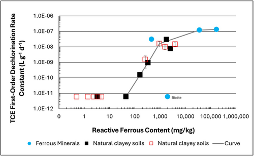
Figure 1: First-order rate constants for abiotic reductive dechlorination of TCE under anaerobic conditions. Circles are data from Schaefer
et al., 2021
[4], filled squares from Schaefer
et al., 2018
[5], and Schaefer
et al., 2017
[6], and open squares from Schaefer
et al., 2025
[1].
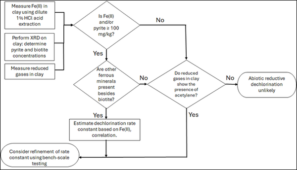
Figure 2: Flowchart diagram of field screening procedures
The recommended approach builds upon the methodology and findings of a recent study[1], emphasizing field-based and analytical techniques to quantify abiotic first-order reductive dechlorination rate constants for PCE and TCE in clayey soils under anoxic conditions. Key components of this evaluation are listed below:
- Zone Identification: The focus of the investigation should be to delineate clayey zones adjacent to hydraulically conductive zones.
- Ferrous Mineral Quantification: Assess ferrous mineral context in clay via 1% HCl extraction at ambient temperature over a 10-minute interval.
- Mineralogical Characterization: Conduct XRD analysis with the specific intent of identifying the presence of pyrite and biotite.
- Reduced Gas Analysis: Measurement of reduced gases such as acetylene, ethene, and ethane concentrations in clay samples. Gas-tight sampling devices (e.g., En Core® soil samplers by En Novative Technologies, Inc.) should be used to ensure sample integrity during collection and transport.
Clay samples should be collected within a few centimeters of the high-permeability interface, with optional additional sampling further inward. For mineralogical analysis, a defined interval may be collected and subsequently subsampled. To preserve sample integrity, exposure to air should be minimized during collection, transport, and handling. Homogenization should occur within an anaerobic chamber, and if subsamples are required for external analysis, they must be shipped in gas-tight, anaerobic containers.
Estimation of the abiotic reductive first-order rate constant for PCE and TCE is based on the “reactive” ferrous content in the clay. Reactive ferrous content (Fe(II)r) is estimated as shown in Equation 1:
- Equation 1: Fe(II)r = DA + XRDpyr - XRDbiotite
where DA is the ferrous content from the dilute acid (1% HCl) extraction, XRDpyr is the pyrite content from XRD analysis, and XRDbiotite is the biotite content from XRD analysis[1].
Abiotic dechlorination is unlikely to contribute to mitigating contaminant back-diffusion when reactive ferrous iron (Fe(II)r) concentrations are below 100 mg/kg (Figure 1). For Fe(II)r above 100 mg/kg, the first-order rate constant for PCE and TCE reductive dechlorination can be estimated using the correlation shown in Figure 1[5][7]. The rate constant exhibits a strong positive correlation with the logarithm of reactive Fe(II) content (Pearson’s r = 0.82), with a slope of 4.7 × 10⁻⁸ L g⁻¹ d⁻¹ (log mg kg⁻¹)⁻¹.
Figure 2 presents a decision flowchart designed to evaluate the significance and extent of abiotic reductive dechlorination. By applying Equation 1 to the dilute acid extractable Fe(II) plus measured mineral species data from clay samples, the reactive ferrous iron content (Fe(II)r) can be quantified, enabling a streamlined assessment of the extent to which abiotic processes are contributing to the mitigation of contaminant back-diffusion.
If Fe(II)r is ≥ 100 mg/kg, a first-order dechlorination rate constant can be estimated and subsequently used within a contaminant fate and transport model. However, if acetylene is detected in the clay, even with Fe(II)r less than 100 mg/kg, then bench-scale testing using methods similar to those described in a recent study[1] is recommended, as such results would likely be inconsistent with those shown in Figure 1, suggesting some other mechanism might be involved, or that the system mineralogy might be more complex than anticipated. Even if Fe(II)r ≥ 100 mg/kg, confirmatory bench-scale testing may be conducted for additional verification and to refine estimation of the abiotic dechlorination rate constant.
Summary and Recommendations
The approach outlined above is intended to serve as a generalized guide for practitioners and site managers to cost-effectively determine the extent to which beneficial abiotic reductive dechlorination reactions are likely occurring in low permeability (e.g., clayey) zones. This approach may be contraindicated if co-contaminants are present. It is currently unclear whether other classes of potentially reactive chemicals, such as trinitrotoluene (TNT) or chlorinated ethanes, could interact competitively with PCE and TCE.
In addition, it remains unclear how other classes of compounds such as per- and polyfluoroalkyl substances (PFAS) may interact or sorb with ferrous minerals and potentially inhibit abiotic dechlorination reactions. Coupling these recommended activities with conventional site investigation tasks would provide an opportunity to perform many of the up-front screening activities with minimal additional project costs. It is important to note that the guidance proposed herein pertains to particularly low permeability media. Sites with complex or varying lithology, where the mineralogy and/or redox conditions may vary, might require evaluation of multiple samples to provide appropriate site-wide information.
References
- ^ 1.0 1.1 1.2 1.3 1.4 Schaefer, C.E., Tran, D., Nguyen, D., Latta, D.E., Werth, C.J., 2025. Evaluating Mineral and In Situ Indicators of Abiotic Dechlorination in Clayey Soils. Groundwater Monitoring and Remediation, 45(2), pp. 31-39. doi: 10.1111/gwmr.12709
- ^ Falta, R., and Wang, W., 2017. A semi-analytical method for simulating matrix diffusion in numerical transport models. Journal of Contaminant Hydrology, 197, pp. 39-49. doi: 10.1016/j.jconhyd.2016.12.007 Open Access Manuscript
- ^ Kulkarni, P.R., Adamson, D.T., Popovic, J., Newell, C.J., 2022. Modeling a well-charactized perfluorooctane sulfate (PFOS) source and plume using the REMChlor-MD model to account for matrix diffusion. Journal of Contaminant Hydrology, 247, Article 103986. doi: 10.1016/j.jconhyd.2022.103986 Open Access Manuscript
- ^ Schaefer, C.E., Ho, P., Berns, E., Werth, C., 2021. Abiotic dechlorination in the presence of ferrous minerals. Journal of Contaminant Hydrology, 241, 103839. doi: 10.1016/j.jconhyd.2021.103839 Open Access Manuscript
- ^ 5.0 5.1 Schaefer, C.E., Ho, P., Berns, E., Werth, C., 2018. Mechanisms for abiotic dechlorination of trichloroethene by ferrous minerals under oxic and anoxic conditions in natural sediments. Environmental Science and Technology, 52(23), pp.13747-13755. doi: 10.1021/acs.est.8b04108
- ^ Schaefer, C.E., Ho., Gurr, C., Berns, E., Werth, C., 2017. Abiotic dechlorination of chlorinated ethenes in natural clayey soils: impacts of mineralogy and temperature. Journal of Contaminant Hydrology, 206, pp. 10-17. doi: 10.1016/j.jconhyd.2017.09.007 Open Access Manuscript
- ^ Borden, R.C., Cha, K.Y., 2021. Evaluating the impact of back diffusion on groundwater cleanup time. Journal of Contaminant Hydrology, 243, Article 103889. doi: 10.1016/j.jconhyd.2021 Open Access Manuscript
See Also

