Difference between revisions of "User:Jhurley/sandbox"
(→PFAS Treatment by Anion Exchange) |
(→PFAS Treatment by Anion Exchange) |
||
| Line 1: | Line 1: | ||
==PFAS Treatment by Anion Exchange== | ==PFAS Treatment by Anion Exchange== | ||
| − | + | {| | |
| − | {| id="mp-upper" style="margin:4px 0 0 0; background:none; border-spacing: 0px;" | + | |- |
| + | | | ||
| + | {| id="mp-upper" style="width":70%; margin:4px 0 0 0; background:none; border-spacing: 0px;" | ||
| style="border:1px solid transparent; " | | | style="border:1px solid transparent; " | | ||
| class="MainPageBG" style="border:1px solid #cedff2; background:#f5faff; vertical-align:top;" | | | class="MainPageBG" style="border:1px solid #cedff2; background:#f5faff; vertical-align:top;" | | ||
| Line 41: | Line 43: | ||
|} | |} | ||
|} | |} | ||
| + | |} | ||
| + | {| id="mp-upper" style="width":30%; margin:4px 0 0 0; background:none; border-spacing: 0px;" | ||
| + | | style="border:1px solid transparent; " | | ||
| + | | class="MainPageBG" style="border:1px solid #cedff2; background:#f5faff; vertical-align:top;" | | ||
| + | {| id="mp-left" style="width:100%; vertical-align:top; background:#f5faff;" | ||
| + | |- | ||
| + | | style="padding:2px; width:100%" |<h2 id="mp-otd-h2" style="margin:3px; background:#cedff2; font-family:inherit; font-size:120%; font-weight:bold; border:1px solid #a3b0bf; text-align:left; color:#000; padding:0.2em 0.4em;">Development Team</h2> | ||
| + | |- | ||
| + | || | ||
| + | |- | ||
| + | | '''Executive Editor''' | ||
| + | |- | ||
| + | | Bilgen Yuncu, PhD, PE | ||
| + | |- | ||
| + | | TRC, Cary NC | ||
| + | |- | ||
| + | || | ||
| + | |- | ||
| + | | Technical Editor | ||
| + | |- | ||
| + | | Jim Hurley, MS, EIT | ||
| + | |- | ||
| + | | TRC, Cary NC | ||
| + | |- | ||
| + | || | ||
| + | |- | ||
| + | | Debra Tabron | ||
| + | |- | ||
| + | | Administrative Assistant | ||
| + | |- | ||
| + | | TRC, Cary NC | ||
|} | |} | ||
Revision as of 12:37, 31 May 2024
PFAS Treatment by Anion Exchange
| ||||||||||||||||||||||||||||||||||||||||||
Anion exchange has emerged as one of the most effective and economical technologies for treatment of water contaminated by per- and polyfluoroalkyl substances (PFAS). Anion exchange resins (AERs) are polymer beads (0.5–1 mm diameter) incorporating cationic adsorption sites that attract anionic PFAS by a combination of electrostatic and hydrophobic mechanisms. Both regenerable and single-use resin treatment systems are being investigated, and results from pilot-scale studies show that AERs can treat much greater volumes of PFAS-contaminated water than comparable amounts of granular activated carbon (GAC) adsorbent media. Life cycle treatment costs and environmental impacts of anion exchange and other adsorbent technologies are highly dependent upon the treatment criteria selected by site managers to determine when media is exhausted and requires replacement or regeneration. Related Article(s):
Contributor(s):
Key Resource(s):
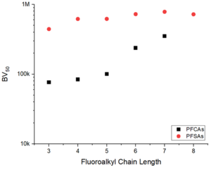
Introduction Figure 2. Effect of perfluoroalkyl carbon chain length on the estimated bed volumes (BVs) to 50% breakthrough of PFCAs and PFSAs observed in a pilot study[3] treating PFAS-contaminated groundwater with the PFAS-selective AER (Purolite PFA694E) Anion exchange is an adsorptive treatment technology that uses polymeric resin beads (0.5–1 mm diameter) that incorporate cationic adsorption sites to remove anionic pollutants from water[4]. Anions (e.g., NO3-) are adsorbed by an ion exchange reaction with anions that are initially bound to the adsorption sites (e.g., Cl-) during resin preparation. Many per- and polyfluoroalkyl substances (PFAS) of concern, including perfluorooctanoic acid (PFOA) and perfluorooctane sulfonate (PFOS), are present in contaminated water as anionic species that can be adsorbed by anion exchange reactions[1][5][6].
Resins most commonly applied for PFAS treatment are strong base anion exchange resins (SB-AERs) that incorporate quaternary ammonium cationic functional groups with hydrocarbon side chains (R-groups) that promote PFAS adsorption by a combination of electrostatic and hydrophobic mechanisms (Figure 1)[1][7]. SB-AERs maintain cationic functional groups independent of water pH. Recently introduced ‘PFAS-selective’ AERs show >1,000,000-fold greater selectivity for some PFAS over the Cl- initially loaded onto resins[8]. These resins also show much higher adsorption capacities for PFAS (mg PFAS adsorbed per gram of adsorbent media) than granular activated carbon (GAC) adsorbents. PFAS of concern include a wide range of structures, including perfluoroalkyl carboxylic acids (PFCAs) and perfluoroalkyl sulfonic acids (PFSAs) of varying carbon chain length[9]. As such, affinity for adsorption to AERs is heavily dependent upon PFAS structure[1][5]. In general, it has been found that the extent of adsorption increases with increasing chain length, and that PFSAs adsorb more strongly than PFCAs of similar chain length (Figure 2)[8][10]. The chain length-dependence supports the conclusion that PFAS-resin hydrophobic mechanisms contribute to adsorption. Adsorption of polyfluorinated structures also depend on structure and prevailing charge, with adsorption of zwitterionic species (containing both anionic and cationic groups in the same structure) to AERs being documented despite having a net neutral charge[8]. Reactors for Treatment of PFAS-Contaminated WaterAnion exchange treatment of water is accomplished by pumping contaminated water through fixed bed reactors filled with AERs (Figure 3). A common configuration involves flowing water through two reactors arranged in a lead-lag configuration[11]. Water flows through the pore spaces in close contact with resin beads. Sufficient contact time needs to be provided, referred to as empty bed contact time (EBCT), to allow PFAS to diffuse from the water into the resin structure and adsorb to exchange sites. Typical EBCTs for AER treatment of PFAS are 2-5 min, shorter than contact times recommended for granular activated carbon (GAC) adsorbents (≥10 min)[12][13]. The higher adsorption capacities and shorter EBCTs of AERs enable use of much less media and smaller vessels than GAC, reducing expected capital costs for AER treatment systems[14]. Like other adsorption media, PFAS will initially adsorb to media encountered near the inlet side of the reactor, but as ion exchange sites become saturated with PFAS, the active zone of adsorption will begin to migrate through the packed bed with increasing volume of water treated. Moreover, some PFAS with lower affinity for exchange sites (e.g., shorter-chain PFAS that are less hydrophobic) will be displaced by competition from other PFAS (e.g., longer-chain PFAS that are more hydrophobic) and move further along the bed to occupy open sites[15]. Eventually, PFAS will start to breakthrough into the effluent from the reactor, typically beginning with the shorter-chain compounds. The initial breakthrough of shorter-chain PFAS is similar to the behavior observed for AER treatment of inorganic contaminants. Upon breakthrough, treatment is halted, and the exhausted resins are either replaced with fresh media or regenerated before continuing treatment. Most vendors are currently operating AER treatment systems for PFAS in single-use mode where virgin media is delivered to replace exhausted resins, which are transported off-site for disposal or incineration[1]. As an alternative, some providers are developing regenerable AER treatment systems, where exhausted resins are regenerated on-site by desorbing PFAS from the resins using a combination of salt brine (typically ≥1 wt% NaCl) and cosolvent (typically ≥70 vol% methanol)[1][16][17]. This mode of operation allows for longer term use of resins before replacement, but requires more complex and extensive site infrastructure. Cosolvent in the resulting waste regenerant can be recycled by distillation, which reduces chemical inputs and lowers the volume of PFAS-contaminated still bottoms requiring further treatment or disposal[16]. Currently, there is active research on various technologies for destruction of PFAS concentrates in AER still bottoms residuals[3][18]. Field DemonstrationsField pilot studies are critical to demonstrating the effectiveness and expected costs of PFAS treatment technologies. A growing number of pilot studies testing the performance of commercially available AERs to treat PFAS-contaminated groundwater, including sites impacted by historical use of aqueous film-forming foam (AFFF), have been published recently (Figure 4)
In comparison to other reported PFAS destruction techniques, PRD offers several advantages:
Disadvantages
State of the ArtTechnical Performance
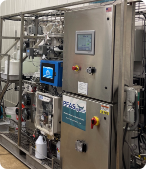
Bench scale PRD tests were performed for the following samples collected from Department of Defense sites: groundwater (GW), groundwater foam fractionate (FF), firefighting truck rinsate ( AFFF Rinsate), 3M Lightwater AFFF, investigation derived waste nanofiltrate (IDW NF), ion exchange still bottom (IX SB), and Ansulite AFFF. The PRD treatment was more effective in low conductivity/TDS solutions. Generally, PRD reaction rates decrease for solutions with a TDS > 10,000 ppm, with an upper limit of 30,000 ppm. Ansulite AFFF and IX SB samples showed low destruction efficiencies during initial screening tests, which was primarily attributed to their high TDS concentrations. Benchtop testing data are shown in Table 1 for the remaining five sample matrices. During treatment, PFOS and PFOA concentrations decreased 96% to >99% and 77% to 97%, respectively. For the PFAS with proposed drinking water Maximum Contaminant Levels (MCLs) recently established by the USEPA (PFNA, PFOA, PFOS, PFHxS, PFBS, and HFPO-DA), concentrations decreased >99% for GW, 93% for FF, 95% for AFFF Rinsate and IDW NF, and 79% for AFFF (diluted 10x) during the treatment time allotted. Meanwhile, the total PFAS concentrations, including all 40 known PFAS analytes and unidentified perfluorocarboxylic acid (PFCA) precursors, decreased from 34% to 96% following treatment. All of these concentration reduction values were calculated by using reporting limits (RL) as the concentrations for non-detects. Excellent fluorine/fluoride mass balance was achieved. There was nearly a 1:1 conversion of organic fluorine to free inorganic fluoride ion during treatment of GW, FF and AFFF Rinsate. The 3M Lightwater AFFF (diluted 10x) achieved only 65% fluorine mass balance, but this was likely due to high adsorption of PFAS to the reactor. ApplicationDue to the first-order kinetics of PRD, destruction of PFAS is most energy efficient when paired with a pre-concentration technology, such as foam fractionation (FF), nanofiltration, reverse osmosis, or resin/carbon adsorption, that remove PFAS from water. Application of the PFASigatorTM is therefore proposed as a part of a PFAS treatment train that includes a pre-concentration step. The first pilot study with the PFASigatorTM was conducted in late 2023 at an industrial facility in Michigan with PFAS-impacted groundwater. The goal of the pilot study was to treat the groundwater to below the limits for regulatory discharge permits. For the pilot demonstration, the PFASigatorTM was paired with an FF unit, which pre-concentrated the PFAS into a foamate that was pumped into the PFASigatorTM for batch PFAS destruction. Residual PFAS remaining after the destruction batch was treated by looping back the PFASigatorTM effluent to the FF system influent. During the one-month field pilot duration, site-specific discharge limits were met, and steady state operation between the FF unit and PFASigatorTM was achieved such that the PFASigatorTM destroyed the required concentrated PFAS mass and no off-site disposal of PFAS contaminated waste was required. References
See Also |
|||||||||||||||||||||||||||||||||||||||||||||||||||||||||||||||||||||||||||||||||||||||||||||||||

