Difference between revisions of "Source Zone Modeling"
m (1 revision imported) |
m (1 revision imported) |
||
| (20 intermediate revisions by 2 users not shown) | |||
| Line 49: | Line 49: | ||
[[File:Falta_source_Fig3.jpg|thumbnail|left|650px|Figure 3. Numerical simulation of source zone dissolution of TCE DNAPL pools in vertical slice into an aquifer (adapted from Falta, (2003)<ref name= "Falta2003DNAPL" />). The concentration units are in g/L, the y-axis represents depth in meters, and the x-axis the horizontal distance in meters.]] | [[File:Falta_source_Fig3.jpg|thumbnail|left|650px|Figure 3. Numerical simulation of source zone dissolution of TCE DNAPL pools in vertical slice into an aquifer (adapted from Falta, (2003)<ref name= "Falta2003DNAPL" />). The concentration units are in g/L, the y-axis represents depth in meters, and the x-axis the horizontal distance in meters.]] | ||
| − | The specific choice of model depends on both the contaminant and the remediation method. Some of these codes can simulate [[ | + | The specific choice of model depends on both the contaminant and the remediation method. Some of these codes can simulate [[Thermal Remediation | thermal remediation]] of NAPL source zones (STOMP, NUFT, MUFTE, T2VOC, TMVOC), while others are designed for modeling surfactant floods (UTCHEM). Numerical source zone models designed for modeling NAPL source zones are summarized in the literature<ref name= "Gerhard2014">Gerhard, J.I., Kueper, B.H. and Sleep, B.E., 2014. Modeling Source Zone Remediation. In Chlorinated Solvent Source Zone Remediation, pgs. 113-144. Springer, New York. [https://doi.org/10.1007/978-1-4614-6922-3_5 doi: 10.1007/978-1-4614-6922-3_5]</ref>. For sites containing metals or radionuclides, multiphase reactive transport models can be used (such as TOUGHREACT<ref name= "Xu2008" />). |
The general approach with these types of models would be to represent the 3D heterogeneity and contaminant distribution to the extent possible, and simulate the remediation process. The contaminant discharge from the source to the plume can be determined by allowing groundwater to flow through the model before, during, and after the remediation process. | The general approach with these types of models would be to represent the 3D heterogeneity and contaminant distribution to the extent possible, and simulate the remediation process. The contaminant discharge from the source to the plume can be determined by allowing groundwater to flow through the model before, during, and after the remediation process. | ||
Latest revision as of 15:57, 4 May 2018
Source zone modeling involves mathematical simulations of contaminant behavior in areas that act as sources of groundwater contamination. Contaminant mass discharge from source zones causes groundwater plumes to develop, and source attenuation and remediation can be a critical part of the overall site remediation effort. Source zone modeling can be used to assess the likely effectiveness and benefits of source remediation and better understand source zone monitored natural attenuation (MNA).
Related Article(s):
Contributor(s): Dr. Ron Falta
Key Resource(s):
- REMChlor remediation evaluation model for chlorinated solvents user’s manual[1]
- Modeling plume responses to source treatment[2]
Introduction
Groundwater contaminant plumes typically develop from concentrated, localized source areas. In most instances, these source areas are much smaller than the more dilute dissolved contaminant plumes that develop downgradient. Source zone remediation is often aggressive and expensive, involving excavation, or the application of heat or strong oxidants. In contrast, plume remediation tends to involve less intense efforts, and typically focuses on enhancing naturally occurring biological or abiotic reactions. Given the different nature of the physical processes that occur in source and plume zones, different types of models are often used for the two zones.
Source Zone Modeling
There are two main approaches to simulating source zone remediation and the discharge of contaminants from the source zone into the plume. A simple and practical approach for small sites involves the use of analytical mass balance models of the source zone that relate source zone contaminant mass to the source zone contaminant discharge[3]. The most comprehensive approach involves sophisticated 3D multiphase flow numerical models that can simulate the physical and chemical processes that occur during source zone remediation. Source zone models can be used to many several questions, but the most common are:
- How do I get the source zone concentration vs. time data that is needed in a numerical groundwater plume response model?
- How much will intensive source remediation reduce the remediation timeframe?
- How long will it take for groundwater in the source zone to attenuate naturally to a particular cleanup standard[4]?
Analytical Source Models
Although contaminant transport and remediation in the source zone is complex and uncertain, a general observation is that contaminant discharge from the source zone tends to monotonically decrease as the source mass is depleted[2]. Mathematically this is the same as assuming the source concentration (and mass discharge) follows a first order decay pattern over time. This type of assumption was applied in simple “box models” of the source zone built into the BIOSCREEN model[5] and BIOCHLOR models[6] where source decay was assumed to be a first order process. The user enters the source mass, data to calculate the initial mass discharge leaving the source, and then the box model simulates the attenuation of the source over time. The SourceDK model[7] and Natural Attenuation Software (NAS)[8] also use a box model approach. A more powerful type of box model also is the use of a simple power function to relate source discharge to source mass[9][10][11][12]. Specifically, the source zone power function can be written as:
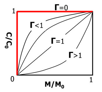
where Cs is the time-dependent average contaminant concentration leaving the source zone, C0 is the initial concentration leaving the source zone (before remediation or natural attenuation), M is the time-dependent mass in the source zone, and M0 is the initial mass in the source zone. The exponent Γ is a fitting parameter that determines the shape of the discharge vs. mass curve (Fig. 1).
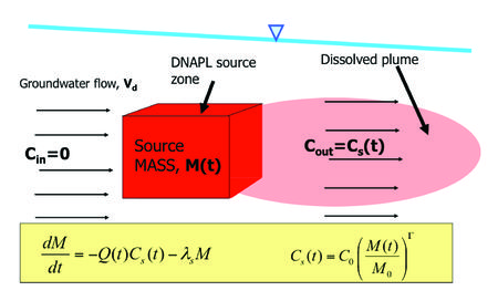
The source zone power function exponent is often close to 1, and typically ranges from ~ 0.5 to 2[13][14]. For the special case of Γ=1, the source discharge and mass are linearly related. The power function (equation 1) can be used to form the basis of a mass balance of the source zone. Taking a simplified approach, the source zone is treated like a “black box”, which is characterized as containing some contaminant mass, and producing some contaminant discharge (Fig. 2). The resulting differential equation can be solved to give the time-dependent source mass and source discharge functions[11][12][13][15]. This type of source model can also account for source remediation by considering rapid removal of part or all of the source mass at some time[13][14]. The REMChlor Model for use at chlorinated solvent sites[1] and REMFuel model for use at hydrocarbon sites[16] are public domain models with the power function programmed into the source terms.
Numerical Source Models
Most commonly used numerical models don’t include source zone models, but require the user to either: 1) assume constant source zone concentrations over time, or 2) enter in source concentrations vs. time data directly from some other source attenuation model[17][4]. There many groundwater modeling studies using numerical models also have a separate model to obtain source attenuation data.
Advanced 3D multiphase flow numerical simulations can be used to model source remediation activities. A multiphase approach is used when contaminants are present above the water table in the vadose zone, and when non-aqueous phase liquid (NAPLs) are present. Several 3D multiphase flow and transport models are available. Most simulate the flow of gas, water, and NAPL phases in heterogeneous systems and fractured media with capillary pressure and relative permeability effects. They are usually fully compositional so that contaminants can be present in all phases with local scale mass transfer between the phases. Some examples of multiphase flow source remediation codes include:
DNAPL3D[18][19]; COMPSIM[20] [21]; UTCHEM[22]; T2VOC[23]; TMVOC[24]; TOUGHREACT[25]; MVALOR[26][27]; STOMP[28]; CompFlow[29]; NUFT[30].

The specific choice of model depends on both the contaminant and the remediation method. Some of these codes can simulate thermal remediation of NAPL source zones (STOMP, NUFT, MUFTE, T2VOC, TMVOC), while others are designed for modeling surfactant floods (UTCHEM). Numerical source zone models designed for modeling NAPL source zones are summarized in the literature[32]. For sites containing metals or radionuclides, multiphase reactive transport models can be used (such as TOUGHREACT[25]).
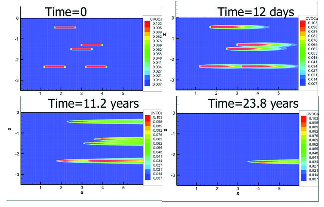
The general approach with these types of models would be to represent the 3D heterogeneity and contaminant distribution to the extent possible, and simulate the remediation process. The contaminant discharge from the source to the plume can be determined by allowing groundwater to flow through the model before, during, and after the remediation process. A straightforward example of the numerical approach is a 2D model of dense NAPL (DNAPL) pool dissolution (Fig. 3)[31]. In this model, thin, rectangular trichloroethene (TCE) DNAPL pools were placed within a homogeneous porous media, with a hydraulic gradient from left to right. As groundwater flows through and past the DNAPL, it dissolves and exits the model at the downstream (right) face. Over time, the DNAPL pools slowly dissolve, and the source zone discharge decreases.
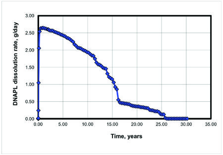
The TCE mass flux distribution and mass discharge exiting the right side of this model would represent the source loading to the downgradient plume. The source discharge changes versus time results show, for the example pool dissolution case (Fig. 3), that the TCE mass discharge to the plume would gradually decrease over the 25-year life of the DNAPL pools (Fig. 4).
Numerical source zone models can consider more complicated heterogeneous systems, and simulate processes such as thermal remediation, in-situ chemical oxidation, bioremediation, soil vapor extraction, air sparging, and chemical immobilization (see discussion in Gerhard et al. (2014)[32]).

Numerical Model Limits and Uncertainty
The numerical modeling approach for simulating source remediation and its effect on source discharge has some significant limitations and drawbacks. The most important limitation is the lack of detailed 3-D information on local heterogeneity and contaminant distributions at many sites. In many instances, the mass of contaminant released, and the timing and exact location of the release are unknown. Furthermore, even high-resolution sampling may not be sufficient to fully delineate the presence of DNAPL pools and ganglia if they are present. This lack of knowledge about the NAPL architecture may limit the reliability of the detailed numerical model predictions. The numerical source zone models also tend to be complex, and require substantial experience and time to setup and run. In general, they are used much less frequently than numerical models for plumes (see Plume Response Modeling). The numerical source zone models have proven to be useful in a research setting, and for simulating enhanced recovery techniques such as steam injection and surfactant flooding.
Matrix Diffusion in Sources
There is a growing consensus that molecular diffusion of contaminants into and out of low permeability zones can play a significant and even dominant role in source attenuation and remediation modeling. Most analytical models can approximate matrix diffusion by using a box model with a first order decay assumption or by using a power function model with gamma ≥ 1.0. This generates a long concentration vs. time tail that is observed at many sites affected by matrix diffusion (“long tail”) even after the Non-Aqueous Phase Liquids (NAPL) are gone (e.g., Seyedabbasi et al. (2012)[33]). The Matrix Diffusion Toolkit[34] can be used to simulate matrix diffusion effects directly with a choice of two separate analytical models. Most of the numerical source zone models described above model the dissolution of the NAPL but do not include any matrix diffusion effects unless low permeability zones are explicitly included along with the diffusion mechanism. Therefore these models will likely underestimate the concentrations in the source zone after the NAPL is removed and underestimate the remediation timeframe.
Summary
Source zone models simulate source remediation and contaminant discharge from the source zone. Both analytical and numerical models are used for these simulations. Analytical models are easy to apply, and are appropriate for screening level calculations, and for sites where extensive data are not available. Numerical models can consider a much higher degree of complexity, and may be appropriate where large amounts of data are available. However, numerical models of source behavior tend to be complex and are harder to use than analytical models, and in some cases do not account for matrix diffusion.
References
- ^ 1.0 1.1 Falta, R.W., Stacy, M.B., Ahsanuzzaman, A.N.M., Wang, M. and Earle, R., 2007. REMChlor remediation evaluation model for chlorinated solvents user’s manual Version 1.0. Cent. for subsurface model. support, US Environ. Prot. Agency, Ada, Okla. User's Manual v1.0
- ^ 2.0 2.1 Falta, R.W. and Kueper, B.H., 2014. Modeling plume responses to source treatment. In Chlorinated Solvent Source Zone Remediation, pgs. 145-186. Springer New York. doi: 10.1007/978-1-4614-6922-3_6
- ^ Newell, C.J. and Adamson, D.T., 2005. Planning‐level source decay models to evaluate impact of source depletion on remediation time frame. Remediation Journal, 15(4), 27-47. doi: 10.1002/rem.20058
- ^ 4.0 4.1 Newell, C.J., Kueper, B.H., Wilson, J.T. and Johnson, P.C., 2014. Natural Attenuation of Chlorinated Solvent Source Zones. Chlorinated Solvent Source Zone Remediation, Editors: Kueper, B.H., Stroo, H.F., Vogel, C.M., Ward, C. H., pgs. 459-508. Springer New York. doi: 10.1007/978-1-4614-6922-3
- ^ Newell, C.J., Gonzales, J., and McLeod, R., 1996. BIOSCREEN natural attenuation decision support system, U.S. Environmental Protection Agency. EPA/600/R-96/087. Report pdf
- ^ Aziz, C.E., Smith, A.P., Newell, C.J. and Gonzales, J.R., 2000. BIOCHLOR Chlorinated solvent plume database report. Air Force Center for Environmental Excellence, Texas. Report pdf
- ^ Farhat, S.K., De Blanc, P.C., Newell, C.J., Gonzales, J.R. and Perez, J., 2004. SourceDK remediation timeframe decision support system. User’s Manual. SourceDK
- ^ Chapelle, F.H., Widdowson, M.A., Brauner, J.S., Mendez, E. and Casey, C.C., 2003. Methodology for estimating times of remediation associated with monitored natural attenuation. USGS WRIR, Report 03-4057. 51 pgs. Report pdf
- ^ Rao, P.S.C., Jawitz, J.W., Enfield, C.G., Falta Jr, R.W., Annable, M.D. and Wood, A.L., 2001. Technology integration for contaminated site remediation: clean-up goals and performance metrics. Presented at Groundwater Quality 2001 Sheffield, UK, 6/18-21/2001.
- ^ Rao, P.S.C. and Jawitz, J.W., 2003. Comment on “Steady state mass transfer from single‐component dense nonaqueous phase liquids in uniform flow fields” by TC Sale and DB McWhorter. Water Resources Research, 39(3), 1068. doi: 10.1029/2001WR000599
- ^ 11.0 11.1 Parker, J.C. and Park, E., 2004. Modeling field‐scale dense nonaqueous phase liquid dissolution kinetics in heterogeneous aquifers. Water Resources Research, 40(5). doi: 10.1029/2003WR002807
- ^ 12.0 12.1 Zhu, J. and Sykes, J.F., 2004. Simple screening models of NAPL dissolution in the subsurface. Journal of Contaminant Hydrology, 72(1), 245-258. doi: 10.1016/j.jconhyd.2003.11.002
- ^ 13.0 13.1 13.2 Falta, R.W., Rao, P.S. and Basu, N., 2005. Assessing the impacts of partial mass depletion in DNAPL source zones: I. Analytical modeling of source strength functions and plume response. Journal of Contaminant Hydrology, 78(4), 259-280. doi: 10.1016/j.jconhyd.2005.05.010
- ^ 14.0 14.1 Falta, R.W., 2008. Methodology for comparing source and plume remediation alternatives. Ground Water, 46(2), 272-285. doi: 10.1111/j.1745-6584.2007.00416.x
- ^ Parker, J.C. and Falta, R.W., 2008. Comparison of alternative upscaled model formulations for simulating DNAPL source dissolution and biodecay. Advances in Water Resources, 31(10), 1325-1332. doi: 10.1016/j.advwatres.2008.06.003
- ^ Falta, R.W., Ahsanuzzaman, A.N., Stacy, M.B., Earle, R.C. and Wilson, J.T., 2012. Remediation Evaluation Model for Fuel hydrocarbons (REMFuel). U.S. Environmental Protection Agency. EPA REMFuel
- ^ Rifai, H.S., Borden, R.C., Newell, C.J. and Bedient, P.B., 2010. Modeling remediation of chlorinated solvent plumes. In In Situ Remediation of Chlorinated Solvent Plumes, pgs., 145-184. Springer, New York. doi: 10.1007/978-1-4419-1401-9_6
- ^ Kueper, B.H. and Frind, E.O., 1991. Two‐phase flow in heterogeneous porous media: 1. Model development. Water Resources Research, 27(6), 1049-1057. doi: 10.1029/91WR00266
- ^ Grant, G.P. and Gerhard, J.I., 2007. Simulating the dissolution of a complex dense nonaqueous phase liquid source zone: 2. Experimental validation of an interfacial area–based mass transfer model. Water Resources Research, 43(12). doi: 10.1029/2007WR006039
- ^ Sleep, B.E. and Sykes, J.F., 1993. Compositional simulation of groundwater contamination by organic compounds: 1. Model development and verification. Water resources research, 29(6), 1697-1708. doi: 10.1029/93WR00283
- ^ O'Carroll, D.M. and Sleep, B.E., 2007. Hot water flushing for immiscible displacement of a viscous NAPL. Journal of Contaminant Hydrology, 91(3), 247-266. doi: 10.1016/j.jconhyd.2006.11.003
- ^ Delshad, M., Pope, G.A. and Sepehrnoori, K., 1996. A compositional simulator for modeling surfactant enhanced aquifer remediation, 1 formulation. Journal of Contaminant Hydrology, 23(4), 303-327. doi:10.1016/0169-7722(95)00106-9
- ^ Falta, R.W., Pruess, K., Javandel, I. and Witherspoon, P.A., 1992. Numerical modeling of steam injection for the removal of nonaqueous phase liquids from the subsurface: 1. Numerical formulation. Water Resources Research, 28(2), 433-449. doi: 10.1029/91wr02526
- ^ Pruess, K. and Battistelli, A., 2002. TMVOC, a numerical simulator for three-phase non-isothermal flows of multicomponent hydrocarbon mixtures in saturated-unsaturated heterogeneous media. Report LBNL-49375 Lawrence Berkeley National Laboratory. Report pdf
- ^ 25.0 25.1 Xu, T., 2008. TOUGHREACT user's guide: A simulation program for non-isothermal multiphase reactive geochemical transport in variably saturated geologic media, V1. 2.1. Lawrence Berkeley National Laboratory. Report pdf
- ^ Abriola, L.M., Lang, J.R. and Rathfelder, K., 1997. Michigan soil vapor extraction remediation (MISER) model: a computer program to model soil vapor extraction and bioventing of organic chemicals in unsaturated geological material. US Environmental Protection Agency, National Risk Management Research Laboratory. EPA/600 R-97/099. Report pdf
- ^ Christ, J.A., and L.M. Abriola, 2007. Modeling metabolic reductive dechlorination in dense non-aqueous phase liquid source-zones, Advances in Water Resources, 30, 1547-1561. doi: 10.1016/j.advwatres.2006.05.024
- ^ White, M.D., Oostrom, M. and Lenhard, R.J., 1995. Modeling fluid flow and transport in variably saturated porous media with the STOMP simulator. 1. Nonvolatile three-phase model description. Advances in Water Resources, 18(6), 353-364. doi:10.1016/0309-1708(95)00018-e
- ^ Unger, A.J.A., Forsyth, P.A. and Sudicky, E.A., 1996. Variable spatial and temporal weighting schemes for use in multi-phase compositional problems. Advances in Water Resources, 19(1), 1-27. doi:10.1016/0309-1708(95)00030-M
- ^ Nitao, J.J., 1996. Reference manual for the NUFT flow and transport code. Lawrence Livermore National Laboratory, Report UCRL-ID-113520.
- ^ 31.0 31.1 31.2 Falta, R.W., 2003. Modeling sub‐grid‐block‐scale dense nonaqueous phase liquid (DNAPL) pool dissolution using a dual‐domain approach. Water Resources Research, 39(12). doi: 10.1029/2003WR002351
- ^ 32.0 32.1 Gerhard, J.I., Kueper, B.H. and Sleep, B.E., 2014. Modeling Source Zone Remediation. In Chlorinated Solvent Source Zone Remediation, pgs. 113-144. Springer, New York. doi: 10.1007/978-1-4614-6922-3_5
- ^ Seyedabbasi, M.A., Newell, C.J., Adamson, D.T. and Sale, T.C., 2012. Relative contribution of DNAPL dissolution and matrix diffusion to the long-term persistence of chlorinated solvent source zones. Journal of contaminant hydrology, 134, 69-81. doi: 10.1016/j.jconhyd.2012.03.010
- ^ Farhat, S.K., Newell, C.J., Seyedabbasi, M.A., McDade, J.M., Mahler, N.T., Sale, T.C., Dandy, D.S. and Wahlberg, J.J., 2012. Matrix Diffusion Toolkit. ER-201126. Environmental Security Technology Certification Program (ESTCP) by GSI Environmental Inc., Houston, Texas. ER-201126


