Difference between revisions of "Direct Push Sampling"
m (1 revision imported) |
m (1 revision imported) |
(No difference)
| |
Revision as of 20:05, 3 May 2018
Soil, groundwater, and soil gas samples can be collected by direct push (DP) technology. Both single tube and dual tube DP methods are used for sampling of soils, unconsolidated formations[1][2], and groundwater[1][3][4]. DP methods also may be used to install monitoring wells[1][5][6][7] and soil vapor sampling devices[1][8][9][10].
Related Article(s):
CONTRIBUTOR(S): Wesley McCall, M.S., P.G. and Tom Christy, P.E.
Key Resource(s):
- Using DP Technologies in Site Characterization and Groundwater Monitoring[1]
- US EPA GW Sampling & Monitoring with Direct Push Report[11]
Introduction
Direct push (DP) techniques were first used for cone penetration testing (CPT) in the 1930s[12]. Then as the environmental industry developed it was applied initially to soil vapor sampling in the late 1980s to define the extent of volatile organic contamination. Shortly thereafter soil sampling, groundwater sampling, and groundwater monitoring methods and tools were developed.
DP Soil Sampling
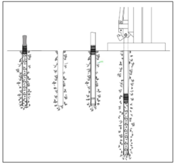
Common DP methods for the collection of soil samples include single-tube and dual-tube approaches[1][2]. Single-tube methods (Fig. 1) utilize a single string of rods or casing to advance the sampler into the subsurface and samples are recovered incrementally as the boring is advanced[13]. These methods are typically more quick and efficient for shallow applications (<20 ft). Samples are tripped out of the boring through the uncased borehole so formation collapse and cross contamination in non-cohesive and saturated formations may be problematic. However, closed piston, single-tube samplers[13] can provide high integrity samples under most formation conditions. Dual tube samplers (Fig. 2) utilize concentric casings to advance the boring[14][15]. The outer casing remains in place as the inner casing is used to trip out the sample as the boring is advanced incrementally. The outer casing prevents borehole collapse and generally reduces the potential for cross contamination between sampling intervals. Unfortunately, dual-tube methods are subject to formation heave when sampling in saturated sands. Under these conditions, water must be added to the outer casing as the samples are removed to prevent fluidized formation from entering the outer casing through the open cutting shoe as the sample is retrieved. Formation heave will complicate and retard the dual-tube sampling process. Under these formation conditions, a closed piston, single-tube sampler may provide higher integrity samples more efficiently. All sample contact equipment should be appropriately decontaminated between samples and locations[16]. All borings should be properly grouted and abandoned[17].
DP Groundwater Sampling
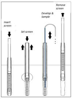
DP methods can provide a rapid and effective means to characterize the distribution of groundwater contamination in unconsolidated materials[1][3][18][19]. Relatively small diameter tools can be advanced into the formation to temporarily set a screen at the desired location and depth[4]. Installation, screen development, sampling, and device removal are often completed in 1 to 2 hours. Development of sandy formations around the screen is often performed with a simple inertial pump and groundwater yield is primarily controlled by local formation permeability. Data quality objectives are used to guide selection of the sampling device and amount of development conducted prior to sample collection. Samples can be collected for most contaminants of concern with a check valve, small bailer, a peristaltic or bladder pump[3][4][20]. When adequately developed, these temporary piezometers may be slug tested[21][22] to obtain information about the local formation hydraulic conductivity, helping to identify migration pathways and quantify risk.
Temporary DP groundwater samplers are available in single-tube and dual-tube designs[4]. Protected screen, single-tube devices are used in many settings to obtain high quality, discrete interval samples[23]. Dual-tube devices (Fig. 3) may be used to perform single depth, discrete interval sampling, or groundwater profiling depending on the tool design and advancement technique applied[24]. Dual-tube systems are subject to formation heave in saturated sands which can complicate and delay progress. Under these conditions, a single-tube, protected screen device[3][4][23] may be preferred.
Specialized multi-port groundwater profilers have been developed to provide details about the vertical distribution of groundwater contaminants and changes in groundwater chemistry[25][26]. Some of these tools simultaneously provide logs (see Direct Push Logging) of variations in formation permeability and/or electrical conductivity.
Grouting with bentonite or cement slurries can be conducted bottom-up using a tremie tube and pump for many of these devices[17]. Sometimes pressure grouting directly through the tool string is most effective. All sample contact parts should be decontaminated between locations[16].
DP Monitoring Well Installation
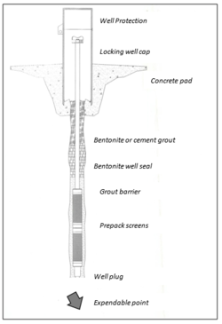
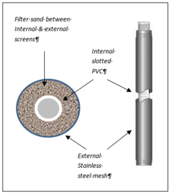
Direct push methods can be used to install monitoring wells (Fig. 4) that range in size from nominal ½ -inch (12 mm) to 2-inch (50 mm) inside diameter[1][3][7]. Single-tube methods are often used with an expendable point to advance the casing to the desired depth. Alternately, dual-tube methods may be used with either a plug on the inner rod string or often by soil coring to advance to depth. Once at depth, a slotted PVC screen with riser is installed through the open bore of the casing to build the well. Because of the smaller diameter of most DP casing, prepacked well screens (Fig. 5) are often used to simplify the well construction process and save time[5][6][27]. Annular seals are typically installed with a small tremie tube and grout pump. Some states limit use of DP wells due to the small grout annulus[7]. The screened formation is developed with an inertial pump or surge block and samples are collected with a bailer, or peristaltic or bladder pump, depending on project requirements. Studies have found that DP installed wells provide representative samples[7][28]. When properly developed, the DP wells can be slug tested[21][22] to assess the local formation hydraulic conductivity.
Soil Vapor Sampling
Direct push methods are used to assess the presence, concentrations and distribution of volatile contaminants in the vadose zone (area above the water table)[29][30][31][32][33][34]. Common sampling approaches include both active soil gas sampling[8][34] and installation of devices that passively collect[35] volatile contaminants over a longer period (days to weeks). To develop an effective soil vapor sampling plan, project managers should understand the site specific soils, geology, and other environmental factors[36][37][38][39].
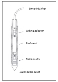
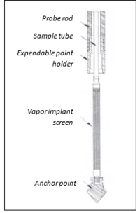
Initial soil gas surveys often involve the installation of small diameter DP rods with an expendable point (Fig. 6). Once installed at the desired depth, tubing with an adapter on the end is lowered down the rods and threaded into the back of the expendable point holder. The drive rods are retracted a fixed distance (often 6 to 12 inches) so that soil vapor from the formation may be sampled through the plastic or stainless steel tube at the surface[34]. Usually the sample train is purged 3 system volumes before the soil gas samples are collected. Measures to test for leaks and verify sample integrity should be conducted at each location[8]. If long term monitoring of soil vapor is required, small diameter (< 0.5-inch/12 mm) screened implants can be installed (Fig. 7). The implants are usually less than 1 ft (30 cm) in length and are made of stainless steel mesh[34]. These devices are installed through small diameter DP rods and a mixture of fine glass beads and bentonite is used to seal the borehole as the drive rods are removed. A small well protector or similar device is placed over the installation to protect it between sampling events. The sample tube should be properly sealed between sampling events to assure sample integrity. If local regulations require a more rigorous installation, or if a longer interval must be monitored, DP monitoring wells may be used for soil vapor sampling and monitoring. Whichever device is installed, it will require purging and sampling. Once the sampling train is purged, the desired gas sampling device is placed in line and sampling is conducted. Some sampling devices include glass gas sampling bulbs, Tedlar bags, or summa canisters[8][34]. These temporary borings must be properly abandoned with bentonite or cement[17] when sampling is completed.
Summary
Direct push methods provide useful methods for sampling of soils, unconsolidated formations, groundwater and soil gas in many settings. The use of single-tube versus dual-tube methods should be guided by project data quality objectives and site specific conditions. DP methods can minimize the generation of waste cuttings and potential worker exposure to hazardous contaminants for many environmental investigations.
References
- ^ 1.0 1.1 1.2 1.3 1.4 1.5 1.6 1.7 McCall, W., Nielsen, D.M., Farrington, S.P., Christy, T.M., 2006. Use of Direct-Push Technologies in Environmental Site Characterization and Ground-Water Monitoring; in Practical Handbook of Environmental Site Characterization and Ground-Water Monitoring, 2nd Edition. Taylor & Francis Group, New York, NY. pgs. 345–471. doi: 10.1201/9781420032246.ch6
- ^ 2.0 2.1 American Society for Testing & Materials International, 2015. D6282. Standard guide for direct push soil sampling for environmental site characterizations. ASTM International, West Conshohocken, PA. doi: 10.1520/D6282_D6282M-14
- ^ 3.0 3.1 3.2 3.3 3.4 U.S. Environmental Protection Agency, 2005. Groundwater sampling and monitoring with direct push technologies. OSWER No. 9200.1-51. EPA 540/R-04-005. Office of Solid Waste and Emergency Response, Washington, D.C. Report pdf
- ^ 4.0 4.1 4.2 4.3 4.4 American Society for Testing & Materials International, 2015. D6001. Standard guide for direct-push groundwater sampling for environmental site characterization. ASTM International, West Conshohocken, PA. doi: 10.1520/D6001-05R12
- ^ 5.0 5.1 American Society for Testing & Materials International, 2015. D6724. Standard guide for installation of direct-push groundwater monitoring wells. ASTM International, West Conshohocken, PA.
- ^ 6.0 6.1 American Society for Testing & Materials International, 2015. D6725. Standard practice of direct-push installation of pre-packed screen monitoring wells in unconsolidated aquifers. ASTM International, West Conshohocken, PA.
- ^ 7.0 7.1 7.2 7.3 Interstate Technology & Regulatory Council, 2006. The Use of direct push well technology for long-term environmental monitoring in groundwater investigations. Interstate Regulatory Council, Sampling, Characterization and Monitoring Team. SCM-2. Washington, D.C. Report pdf
- ^ 8.0 8.1 8.2 8.3 American Society for Testing & Materials International, 2015. D7663. Standard practice for active soil gas sampling in the vadose zone for vapor intrusion evaluations. ASTM International, West Conshohocken, PA. doi: 10.1520/D7663-12
- ^ Interstate Technology & Regulatory Council, 2007. Vapor intrusion pathway: A practical guide. VI-1. ITRC Vapor Intrusion Team, Washington, D.C. Report pdf
- ^ U.S. Environmental Protection Agency, 2015. OSWER Technical guide for assessing and mitigating the vapor intrusion pathway from subsurface vapor source to indoor air. 9200.2-154. Office of Solid Waste and Emergency Response, Washington, D.C., 267 pgs. Report pdf
- ^ U.S. Environmental Protection Agency, 2005. Groundwater sampling and monitoring with direct push technologies. Report pdf
- ^ Lunne, T., Robertson, P.K. and Powell, J.J.M., 1997. Cone penetration testing. Geotechnical Practice. CRC Press, 352 pgs. ISBN 978-0419237501.
- ^ 13.0 13.1 Geoprobe, 2011. Geoprobe® Macro-Core® MC5 1.25-inch light-weight center rod soil sampling system, standard operating procedure. Technical Bulletin No. MK3139. Kejr, Inc., Salina, KS. Report pdf
- ^ Geoprobe, 2013. Geoprobe® DT22 dual tube soil sampling system (continuous core soil sampler) standard operating procedure. Technical Bulletin No. MK3140. Kejr, Inc., Salina, KS. Report pdf
- ^ Geoprobe, 2011. Geoprobe® DT325 dual tube soil sampling system standard operating procedure. Technical Bulletin No. MK3138. Kejr, Inc., Salina, KS. Report pdf
- ^ 16.0 16.1 American Society for Testing & Materials International, 2015. D5088-15A. Standard practice for decontamination of field equipment used at waste sites. ASTM International, West Conshohocken, PA. doi: 10.1520/D5088-15A
- ^ 17.0 17.1 17.2 American Society for Testing & Materials International, 2015. D5299. Standard guide for Decommissioning of Groundwater Wells, Vadose Zone Monitoring Devices, Boreholes and Other Devices for Environmental Activities. ASTM International, West Conshohocken, PA. doi: 10.1520/D5299-99R12E01
- ^ U.S. Environmental Protection Agency, 2005. Expedited site assessment tools for underground storage tank sites, chapter v direct push technologies. EPA 510-B-97-001. Solid Waste and Emergency Response 5403G, Washington, D.C.
- ^ Interstate Technology & Regulatory Council, 2003. Technical and regulatory guidance for the triad approach: A new paradigm for environmental project management (SCM-3). The Interstate Technology & Regulatory Council; Sampling, Characterization and Monitoring Team. Washington, D.C. Report pdf
- ^ McCall, W., 2005. Evaluation of a small mechanical and pneumatic bladder pump for water quality sampling. Ground Water Monitoring & Remediation, 25(2), 142-153. doi: 10.1111/j.1745-6592.2005.0021.x
- ^ 21.0 21.1 Geoprobe, 2011. Geoprobe® DT325 Dual tube soil sampling system standard operating procedure. Technical Bulletin No. MK3138. Kejr, Inc., Salina, KS.
- ^ 22.0 22.1 American Society for Testing & Materials International, 2015. D7242. Standard practice for field pneumatic slug (instantaneous change in head) tests to determine hydraulic properties of aquifers with direct push groundwater samplers. West Conshohocken, PA.
- ^ 23.0 23.1 Geoprobe, 2006. Geoprobe® screen point 16 groundwater sampler, standard operating procedure. Technical Bulletin No. MK3142. Kejr Inc., Salina, Kansas. Report pdf
- ^ Geoprobe, 2010. Geoprobe® screen point 22 groundwater sampler, standard operating procedure. Technical Bulletin No. MK3173. Kejr Inc., Salina, Kansas. Report pdf
- ^ Pitken, S., et. al., 2004. Evaluation of the waterloo profiler as a dynamic site investigation tool. In Proceedings of the Fourth International conference on Remediation of Chlorinated and Recalcitrant Compounds, Paper 1B-07, A.R. Gavaskar and A.S.C. Chen (Eds.), Battelle Press, Columbus, OH.
- ^ McCall, W., Christy, T., and Knabach. M.E, in review. Applying the HPT-GWS for hydrostratigraphy, water quality and aquifer recharge investigations. Groundwater Monitoring & Remediation.
- ^ Geoprobe® 1.—in. X 2.5-in. OD and 1.5-in. X 2.5-in. OD prepacked screen monitoring wells, standard operating procedure. Technical Bulletin No. 992500.
- ^ Kram, M., Lorenzana, D., Michaelsen, J., Major, W., Parker, L., Antworth, C. and McHale, T., 2003. Direct-push wells prove effective for long-term ground water monitoring. Water Well Journal, 57(4), 16-18. Report pdf
- ^ U.S. Environmental Protection Agency, 2015. OSWER Technical guide for assessing and mitigating the vapor intrusion pathway from subsurface vapor source to indoor air. 9200.2-154. Office of Solid Waste and Emergency Response, Washington, D.C. pp 267. Report pdf
- ^ U.S. Environmental Protection Agency, 2015. Technical guide for addressing petroleum vapor intrusion at leaking underground storage tank sites. Office of Underground Storage Tanks, Washington, D.C. EPA 510-R-15-001. Report pdf
- ^ ESTCP, 2007. Recommendations for the Investigation of Vapor Intrusion. Technical Report. ER-200423. ER-200423 Technical Report
- ^ Interstate Technology and Regulatory Council, 2007. Vapor intrusion pathway: Investigative approaches for typical scenarios. VI-1A. Washington, D.C.: Vapor Intrusion Team. Report pdf
- ^ Interstate Technology and Regulatory Council, 2014. Petroleum vapor intrusion: Fundamentals of screening, investigation, and management. PVI-1. Washington, D.C. Petroleum Vapor Intrusion Team. Report pdf
- ^ 34.0 34.1 34.2 34.3 34.4 Geoprobe, 2006. Direct push installation of devices for active soil gas sampling & monitoring. Technical Bulletin No. MK3098. Kejr Inc., Salina, Kansas. Report pdf
- ^ American Society for Testing & Materials International, 2015. D7758. Standard practice for passive soil gas sampling in the vadose zone for source identification, spatial variability assessment, monitoring, and vapor intrusion evaluations. West Conshohocken, PA.
- ^ McHugh, T.E., Beckley, L. and Bailey, D., 2013. Influence of shallow geology on volatile organic chemical attenuation from groundwater to deep soil gas. Groundwater Monitoring & Remediation, 33(3), 92-100. doi:10.1111/gwmr.12013
- ^ Wyatt, D.E., Richers, D.M. and Pirkle, R.J., 1995. Barometric pumping effects on soil gas studies for geological and environmental characterization. Environmental Geology, 25(4), 243-250. doi: 10.1007/BF00766753
- ^ Schumacher, B.A., Zimmerman, J.H., Sibert, C.R., Varner, K.E. and Riddick, L.A., 2009. Macro‐and micro‐purge soil‐gas sampling methods for the collection of contaminant vapors. Groundwater Monitoring & Remediation, 29(1), 138-143. doi:10.1111/j.1745-6592.2009.01222.x
- ^ ESTCP, 2015. Sewers and utility tunnels as preferential pathways for volatile organic compound migration into buildings: risk factors and investigation protocol. Project ER-201505. ER-201505
See Also
- Superfund Website
- General Direct Push Equipment and Tools
- General Direct Push Equipment and Tools – AMS Samplers
- Direct Push Equipment and Tools – 660 Drive Point Profiler
- Expedited Site Assessment Tools – UST
- Use of Dynamic Work Strategies Under a Triad Approach for Site Assessment and Cleanup - Technology Bulletin
- Characterization and Monitoring Technology Descriptions for Cleaning Up Contaminated Sites
- Cryogenic DP Coring
- CPT/SCAPS Thermal Desorption Soil Profiling for VOCs
- CPT/SCAPS Hydrosparge for VOCs
- Demonstration/Validation of DP Well Technology
- Summary of DP Well Comparison Study
- EPA GW Sampling & Mon. with DP Technologies
- Monitoring and Characterization
- Low Stress (Low Flow) Purging and Sampling Procedure for the Collection of Groundwater Samples from Monitoring Wells from January 19, 2010
- Sources of Variability in Groundwater Sampling LTM
- VI Brief Review and Definition
- Basic Introduction to VI *Basic Chemical and Physical Properties of TCE and Exposure Info
- OSWER Technical Guide for Assessing and Mitigating the VI Pathway from Subsurface Vapor Sources to Indoor Air
- Investigation of VI
- Utility Lines for VI
- Demonstration/Validation of Long-Term Monitoring Using Wells Installed by Direct-Push Technologies
